Chapter 3 — System and site requirements
Page 41 of 536
Option 11C Compact
Planning, Installation, Fault Clearing and CCBR Guide
Card slot assignments
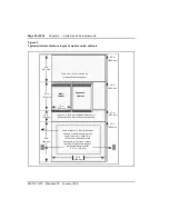
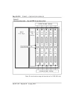
A card slot allocation plan showing circuit card to Peripheral Equipment (PE)
slot assignments (
and
) should be prepared for each cabinet.
NTMW01 Small System Controller (SSC)
The NTMW01 Small System Controller (SSC) card must be installed in the
main cabinet in the CPU slot. It can be equipped with an NTDK22 10m Fiber
Expansion Daughterboard to provide a connection to an expansion cabinet.
NTMW02 Meridian Mail CPU card
The NTMW02 Meridian Mail CPU card must be installed in the main cabinet
in the MMail slot. It can be equipped with up to two NTMW03 4 Port Mail
DSP Daughterboards. Each daughterboard supports four voice mail ports.
NTMW04 DTI/PRI card
The NTMW04 DTI/PRI card must be installed in the main cabinet in any of
slots 1 & 2, 3 & 4 or 5 & 6 (upper PE slots).
The NTMW04 card is recognized by the system as the odd-numbered card
when installed as follows:
•
card 1, when installed in slot 1 & 2
•
card 3, when installed in slot 3 & 4
•
card 5, when installed in slot 5 & 6
Note: This card cannot be installed in the lower PE slots of the main
cabinet (slots 7 through 9) or in any slot of an expansion cabinet.
Line cards
The following Peripheral circuit cards can be installed in any slot in the main
and expansion cabinets:
•
NTMW05 24 Port Digital Line Card
•
NTMW06 16 Port Analog Line Card
Combined Trunk and Line card
The NTMW07 Analog Trunk/Line Card can be installed in any upper PE
slots of the NTMW08 cabinet (main and expansion).
Содержание Meridian Meridian 1
Страница 3: ...553 3121 210 Standard 3 0 January 1999 ...
Страница 17: ...xiv Contents 553 3121 210 Standard 3 0 January 1999 ...
Страница 89: ...Page 70 of 536 Chapter 6 Bracing cabinets against earthquakes 553 3121 210 Standard 3 0 January 1999 ...
Страница 97: ...Page 78 of 536 Chapter 8 Installing a new system 553 3121 210 Standard 3 0 January 1999 ...
Страница 107: ...Page 88 of 536 Chapter 10 Installing the system ground 553 3121 210 Standard 3 0 January 1999 ...
Страница 113: ...Page 94 of 536 Chapter 11 Installing the power supply 553 3121 210 Standard 3 0 January 1999 ...
Страница 125: ...Page 106 of 536 Chapter 12 Adding an expansion cabinet 553 3121 210 Standard 3 0 January 1999 ...
Страница 139: ...Page 120 of 536 Chapter 13 Installing the circuit cards 553 3121 210 Standard 3 0 January 1999 ...
Страница 157: ...Page 138 of 536 Chapter 15 Installing and connecting SDI and Ethernet ports 553 3121 210 Standard 3 0 January 1999 ...
Страница 175: ...Page 156 of 536 Chapter 16 Starting up and testing the system 553 3121 210 Standard 3 0 January 1999 ...
Страница 209: ...Page 190 of 536 Chapter 18 Connecting the trunks 553 3121 210 Standard 3 0 January 1999 ...
Страница 323: ...Page 304 of 536 Chapter 21 Installing Hospitality 553 3121 210 Standard 3 0 January 1999 ...
Страница 419: ...Page 400 of 536 Chapter 23 Pre programmed data 553 3121 210 Standard 3 0 January 1999 ...
Страница 455: ...Page 436 of 536 Chapter 24 Changing pre programmed data 553 3121 210 Standard 3 0 January 1999 ...
Страница 555: ...Page 536 of 536 Chapter 25 Fault locating and clearing 553 3121 210 Standard 3 0 January 1999 ...


