


Digitax HD M753 Control User Guide
83
Issue Number: 3
Pr 00.007 {05.014}
Open Loop Control Mode
There are several voltage modes available which fall into two categories, vector control and fixed boost.
Vector control
Vector control mode provides the motor with a linear voltage characteristic from 0 Hz to motor
Rated Frequency
(00.047), and then a constant voltage above
motor rated frequency. When the drive operates between motor rated frequency/50 and motor rated frequency/4, full vector based stator resistance
compensation is applied. When the drive operates between motor rated frequency/4 and motor rated frequency/2 the stator resistance compensation is
gradually reduced to zero as the frequency increases. For the vector modes to operate correctly the
Rated Power Factor
(00.043),
Stator Resistance
(05.017)
are all required to be set up accurately. The drive can be made to measure these by performing an autotune (see Pr 00.040
Autotune
). The drive can also be
made to measure the stator resistance automatically every time the drive is enabled or the first time the drive is enabled after it is powered up, by selecting
one of the vector control voltage modes.
(0)
Ur S
= The stator resistance is measured and the parameter for the selected motor map is over-written each time the drive is made to run. This test
can only be done with a stationary motor where the flux has decayed to zero. Therefore this mode should only be used if the motor is guaranteed to be
stationary each time the drive is made to run. To prevent the test from being done before the flux has decayed there is a period of 1 second after the drive
has been in the ready state during which the test is not done if the drive is made to run again. In this case, previously measured values are used.
Ur S mode ensures that the drive compensates for any change in motor parameters due to changes in temperature. The new value of stator resistance is
not automatically saved to the drive's EEPROM.
(1)
Ur
= The stator resistance is not measured. The user can enter the motor and cabling resistance into the
Stator Resistance
(05.017). However this will
not include resistance effects within the drive inverter. Therefore if this mode is to be used, it is best to use an autotune test initially to measure the stator
resistance.
(3)
Ur_Auto
= The stator resistance is measured once, the first time the drive is made to run. After the test has been completed successfully the
Open
Loop Control Mode
(00.007) is changed to Ur mode. The
Stator Resistance
(05.017) parameter is written to, and along with the
Open Loop Control Mode
(00.007), are saved in the drive's EEPROM. If the test fails, the voltage mode changes to Ur mode but
Stator Resistance
(05.017) is not updated.
(4)
Ur I
= The stator resistance is measured when the drive is first made to run after each power-up. This test can only be done with a stationary motor.
Therefore this mode should only be used if the motor is guaranteed to be stationary the first time the drive is made to run after each power-up. The new
value of stator resistance is not automatically saved to the drive's EEPROM.
Pr 00.007 {05.014}
Open Loop Control Mode (cont)
Fixed boost
The stator resistance is not used in the control of the motor, instead a fixed characteristic with low frequency voltage boost as defined by parameter Pr
00.008
,
is used. Fixed boost mode should be used when the drive is controlling multiple motors. There are two settings of fixed boost available:
(2)
Fixed
= This mode provides the motor with a linear voltage characteristic from 0 Hz to
Rated Frequency
(00.047), and then a constant voltage above rated
frequency.
(5)
Square
= This mode provides the motor with a square law voltage characteristic from 0 Hz to
Rated Frequency
(00.047), and then a constant voltage
above rated frequency. This mode is suitable for variable torque applications like fans and pumps where the load is proportional to the square of the speed of
the motor shaft. This mode should not be used if a high starting torque is required.
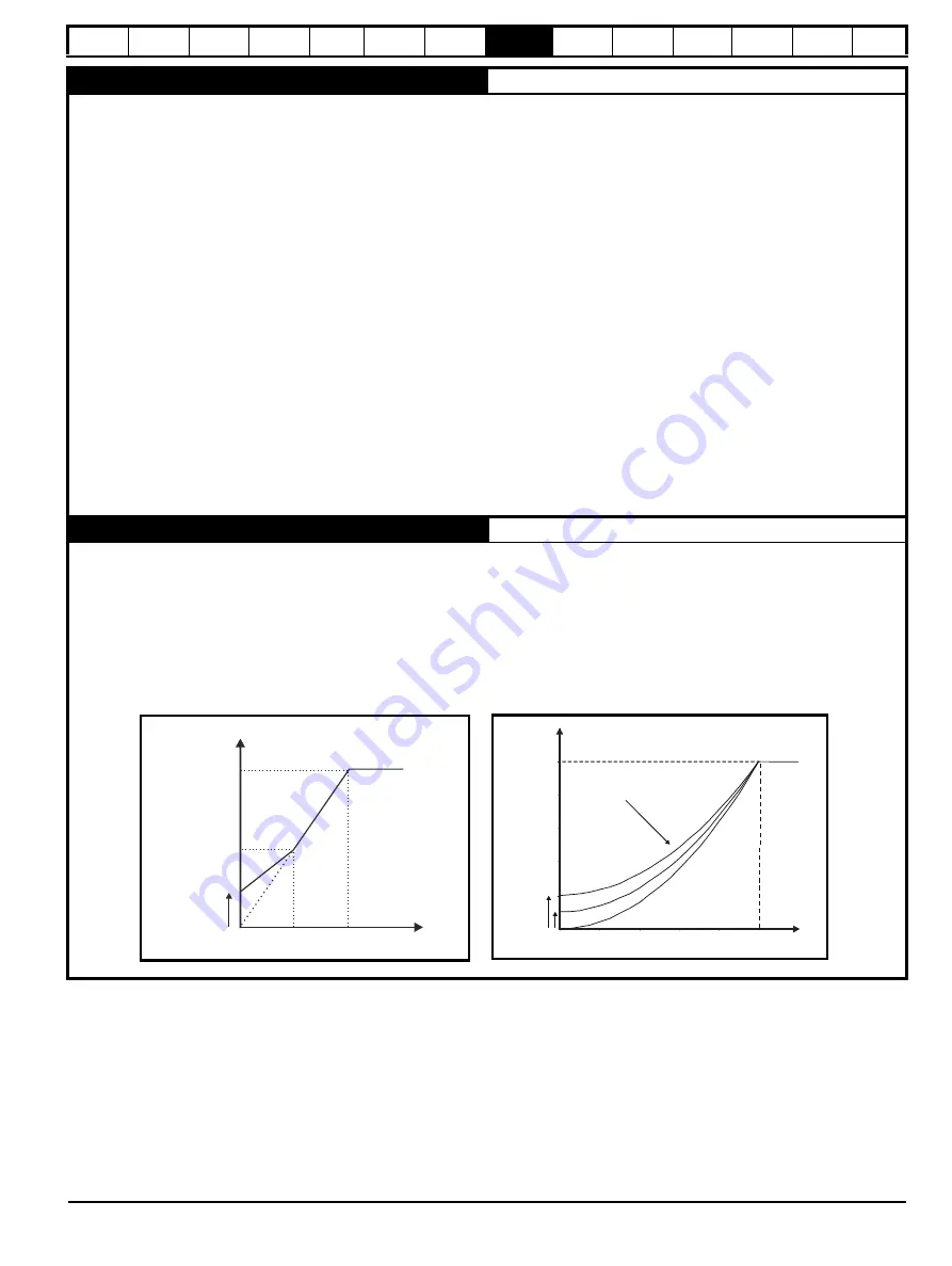
For both these modes, at low frequencies (from 0Hz to ½ x Pr
00.047
) a voltage boost is applied defined by Pr
00.008
as shown below:
Output
voltage
Pr
/ 2
00.044
Pr
00.044
Pr
/
2
00.047
Pr
00.047
Output
frequency
Output voltage characteristic
(Fd)
Voltage boost
Pr
00.008
P
r
00.044
P
r
00.008
P
r
00.047
P
r
+ [(
freq
/P
r
)
x
(P
r
-
P
r
)]
00.008
00.047
00.044
00.008
2
Output voltage characteristic
(
Square
)
O
utput
vo
l
tage
O
utput
frequenc
y
V
o
l
tage
b
oost
Содержание Digitax HD M753 EtherCAT
Страница 261: ......
Страница 262: ...0478 0461 03...