


Digitax HD M753 Control User Guide
105
Issue Number: 3
Some additional configuration of the routing tables within the PC is also
required to allow the PC operating system to know to route the packets
via the PLC. This is standard network routing configuration required
whenever there is a gateway or router between it and the destination
network.
9.15
Additional position loop scaling
For the cases where different feedback devices with different resolutions
are required for the drive velocity loop and the position loop, scaling of
the position loop output will be provided.
When the value of these objects are configured to non-default values,
they will be applied to the AMC scaling ratio. It will be simplified and
multiplied to the AMC output user unit’s ratio.
In order to prevent the overflow risk of AMC scaling parameters, before
the new AMC output user unit’s ratio taking action, it will be checked to
make sure the numerator and the denominator of the multiplied result
are within 1 to 2
31
-1 range. If outside the range, the AMC scaling ratios
will stay at the previous values and the module will trip with
‘APLS Failure’.
This calculation occurs only during certain state transitions.
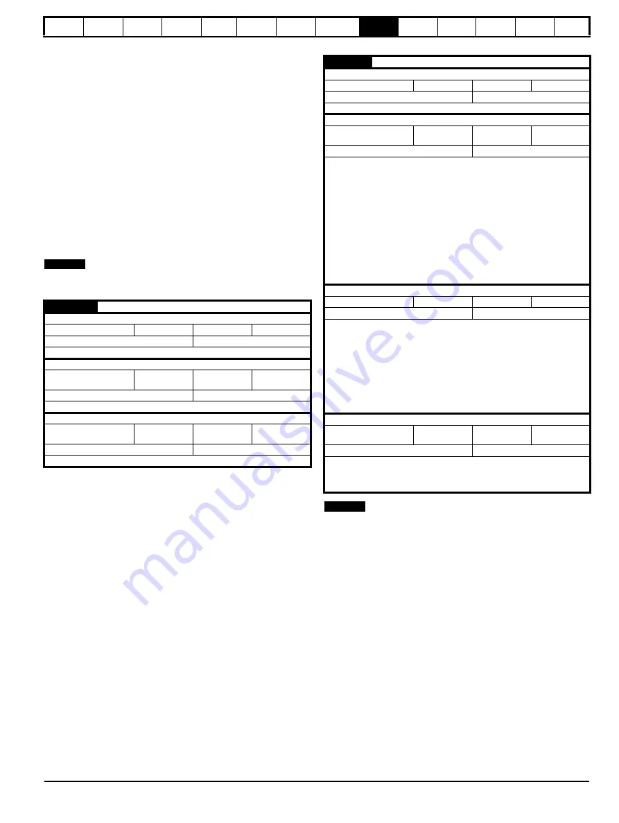
Table 9-32 Additional position loop scaling
9.16
Cyclic data loss behaviour
If the timeout period in sub-index 1 is set to 0 then no PDO loss actions
will occur. If sub-index 1 is set to a non-zero value and no mapped
synchronous PDOs have been accessed for longer than a specified
timeout period according to Sub-index 1, the cyclic data loss behaviour
will occur.
The drive will first be stopped using the Fault reaction option code
object; while this is occurring, the PDO Loss alarm will be set. The cyclic
data loss trip will occur according to the setting in Subindex 2. A setting
will also be provided to allow a cyclic data loss trip to be forced instantly,
if required, regardless of the Fault reaction option code. The number of
missed cyclic data objects will be counted and stored in Sub-index 3.
Cyclic data loss detection is only provided for default data task
configuration (0x3006, 0x3007).
Table 9-33 Cyclic data loss behaviour
There are two mechanisms monitoring the cyclic data communication,
they are cyclic data loss and PDO loss. Cyclic data loss means the
complete cyclic link connection has been lost, for example, unplugging
the EtherCAT cable. PDO loss means one or more PDO data packets
have been lost within one sync cycle, while the cyclic link connection is
still running.
Object 0x3005 configures the behaviour on a cyclic data loss, which
allows the user to define the time period of loosing cyclic data to be
treated as cyclic data loss and what action should the drive take in the
event of it.
In the event of the PDO data not being detected within the
synchronisation cycle the drive will indicate a 'PDOs Lost' alarm.
9.17
Drive profile (CiA402) support
The EtherCAT interface supports the following modes of the CiA402
profile:
•
Homing Mode
•
Cyclic Synchronous Position Mode
•
Interpolated Position Mode
•
vl velocity mode
•
Cyclic Synchronous Velocity Mode
•
Cyclic Synchronous Torque Mode
0x3004
Additional position loop scaling
Sub-index 0
Access: RO
Range: N/A
Size: 1 byte
Unit: N/A
Default: 2
Type:
USINT
Description:
The number of the last sub-index in this object.
Sub-index 1
Access: RW
Range: 1 to
0xFFFFFFFF
Size: 4 bytes
Unit: N/A
Default: 1
Type:
UDINT
Description:
The additional position loop output scaling numerator
Sub-index 2
Access: RW
Range: 1 to
0xFFFFFFFF
Size: 4 bytes
Unit: N/A
Default: 1
Type:
UDINT
Description:
The additional position loop output scaling denominator
NOTE
0x3005
Cyclic data loss behaviour
Sub-index 0
Access: RO
Range: N/A
Size: 1 byte
Unit: N/A
Default: 2
Type:
USINT
Description: The number of the last sub-index in this object.
Sub-index 1
Access: RW
Range: 0 to
65535
Size: 2 byte
Unit: ms
Default: 0
Type:
UINT
Description:
The maximum time, in ms, allowed between accesses to
synchronous PDOs (read or writes). If no PDO access occurs for
this period, the option will start cyclic data loss handling. If a value
of zero is set, no cyclic data loss handling will occur.
When used in modes that provide interpolation, thus having a
mode-specific cycle time, the loss must be for the duration of
(maximum time) cycle. The maximum time will be aligned to the
start of a cycle.
So for a position cycle time of 4 ms and a maximum time
configuration of 6 ms, this would result in a loss detection of
2 cycles or 8 ms of PDO’s.The time will always be rounded up to
the next cycle. If the maximum time is configured to less than the
cycle time then this will be rounded up to the cycle time.
For a time of 0 ms the cyclic data loss detection will not trigger for
any loss.
Sub-index 2
Access: RW
Range: 0 to 3
Size: 1 byte
Unit: N/A
Default: 0
Type:
USINT
Description:
Cyclic Data Loss Action; the value will select an action as follows:
0: a trip will never occur; however, a cyclic data loss will still be
handled by initiating a motor stop according to the Fault reaction
option code and indicating an alarm as previously described.
1: the cyclic data loss trip will occur only after the motor has been
stopped according to the Fault reaction option code; in so far as the
motor stop can actually be detected, depending on the feedback
actually in use, if any.
2: a trip will occur immediately on cyclic data loss (this implies that
the motor will coast; no other motor stop will be initiated).
3: no trip and no motor stop.
Sub-index 3
Access: RO
Range: 0 to
32767
Size: 2 byte
Unit: N/A
Default: 0
Type:
INT
Description:
Cyclic loss counter
Provides an indication of the number of PDO’s lost.
The counter is limited so when it reaches 32767 it stops counting.
The counter is reset when the EtherCAT profile mode is changed.
NOTE
Содержание Digitax HD M753 EtherCAT
Страница 261: ......
Страница 262: ...0478 0461 03...