


Digitax HD M753 Control User Guide
73
Issue Number: 3
7.5.3
P2 position interface
This section shows the parameter settings which must be made to use each of the compatible feedback device types with the P2 position interface on
the drive. For more information on the parameters listed here please refer to the
Parameter Reference Guide
. If the position feedback device
connected to the P2 position interface is required to be used for motor control feedback then Pr
03.026
will need to be set to P2 Drive (1).
Table 7-4 Parameters required for feedback device set-up on the P2 position interface
Information required to be entered by the user.
●
Parameter can be set-up automatically by the drive through auto-configuration. Parameter must be set by the user if auto-configuration is
disabled (i.e. Pr
03.141
= Disabled (0)).
The P2 position interface does not have its own independent power supply output. Therefore, any position feedback device connected to the P2
position interface must either share the P1 power supply output on pin 13 of the 15-way D-type, or be supplied from an external source.
The termination resistors are always enabled on the P2 position interface. Wire break detection is not available when using AB, FD or FR position
feedback device types on the P2 position interface.
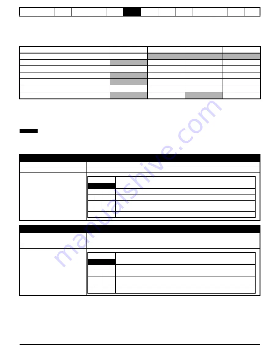
Table 7-4 shows a summary of the parameters required to set-up each feedback device. More detailed information follows.
Parameter
AB, FD, FR
EnDat
SSI
BiSS
P2 Marker Mode
(03.131)
P2 Rotary Turns Bits
(03.133)
●
●
●
P2 Rotary Lines Per Revolution
(03.134)
●
●
●
P2 Comms Bits
(03.135)
●
●
●
P2 Comms Baud Rate
(03.137)
P2 Device Type
(03.138)
P2 Auto–configuration Select
(03.141)
NOTE
Standard quadrature encoder (A, B, Z)
Device Type
(03.138)
AB
(1) for a quadrature encoder
Rotary Line Per Revolution
(03.134)
Set to the number of lines per revolution of the encoder
Marker Mode
(03.131)
Bit
Description
3
2
1
0
x
x
x
1
No action is taken unless marker flag is zero before marker event occurs
x
x
1
x
Pr
03.128
and Pr
03.158
are set to zero
x
1
x
x
Pr
03.128
, Pr
03.129
, Pr
03.130
and the related part of Pr
03.158
are not reset.
Pr
03.158
is transferred to
Pr
03.159
and
Pr
03.132
is set to 1.
1
x
x
x
This Bit in has no effect.
Incremental encoder with Frequency and Direction (F and D), or Forward and Reverse (CW and CCW) signals
Device Type
(03.138)
FD
(2) for frequency and direction signals without commutation signals
FR
(3) for forward and reverse signals without commutation signals
Rotary Line Per Revolution
(03.134)
Set to the number of pulses per revolution of the encoder divided by 2
Marker Mode
(03.131)
Bit
Description
3
2
1
0
x
x
x
1
No action is taken unless marker flag is zero before marker event occurs
x
x
1
x
Pr
03.128
and Pr
03.158
are set to zero
x
1
x
x
Pr
03.128
, Pr
03.129
, Pr
03.130
and the related part of Pr
03.158
are not reset.
Pr
03.158
is transferred to
Pr
03.159
and
Pr
03.132
is set to 1.
1
x
x
x
This Bit in has no effect.
Содержание Digitax HD M753 EtherCAT
Страница 261: ......
Страница 262: ...0478 0461 03...