9
GB
5.
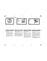
Drill at the outlined points and then, using a ladder, lift the gearmotor until the brackets are placed against the drilled holes and secure by
means of screws and plugs suited to the support surface, as shown in figure 25.
6.
Ensure that the guide is perfectly horizontal, then cut off the excess section of the brackets with a saw, as shown in figure 26.
7.
With the door closed, pull the cord to release carriage (E), as shown in figure 27.
8.
Slide the carriage until the leaf connecting bracket (D) on the upper edge of the door is perfectly perpendicular to the guide (G). Then
secure the leaf connecting bracket (D) with rivets or screws, as shown in figure 28. Use screws or rivets suited to the leaf material, and
ensure that they are able to withstand the maximum force required for leaf opening and closing.
9.
Loosen the screws of the two mechanical stops, then move the front mechanical stop (O) in front of the carriage, as shown in figure 29.
Push the carriage in the closing direction and, on reaching the position, tighten the screw (N) fully down.
10.
Manually open the door to the required opening position, move the rear mechanical stop (Q) next to the carriage, as shown in figure 30
and tighten the screw (P) fully down.
11.
Try to move the door manually. Ensure that the carriage slides easily without friction on the guide and that manual movement does not
require excessive force.
25
26
27
28
29
30
E
G
D
O
N
Q
P
3.3) Installation of the Various Devices
If other devices are needed, install them following the directions pro-
vided in the corresponding instructions. Check this in paragraph “3.5
Description of electrical connections” and the devices which can be
connected to the SPIN in Figure 2.


