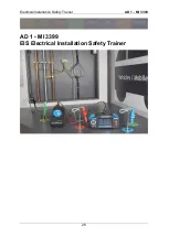
Electrical Installation Safety Trainer
AD 1 - MI 3399
30
2.3.1.3
Fault loop, fault impedance and prospective fault current in RCD protected TN and TT
systems
65
2.3.2
Exercises ........................................................................................................................................ 66
2.3.2.1
Exercise No. 2.3-1: Z
L-PE
and I
PFC
measurement on the supply side ...................................... 66
Measuring connection topology ........................................................................................................ 66
Measuring procedure ......................................................................................................................... 67
Expected results ................................................................................................................................. 68
Expected results with a simulated error ............................................................................................ 69
2.3.2.2
Exercise No. 2.3-2: Z
L-PE
and I
PFC
measurement on the socket side – RCD protected .......... 69
Measuring connection topology ........................................................................................................ 69
Measuring procedure ......................................................................................................................... 70
Expected results ................................................................................................................................. 71
Expected results with a simulated error ............................................................................................ 72
2.4
Measuring RCD parameters ...............................................................................75
2.4.1
Background of measurement ........................................................................................................ 75
2.4.1.1
Function of RCD ................................................................................................................... 76
2.4.2
Exercises ........................................................................................................................................ 78
2.4.2.1
Exercise No. 2.4-1: RCD trip-out time, current and contact voltage measurements .......... 78
Measuring connection topology ........................................................................................................ 78
Measuring procedure ......................................................................................................................... 78
Expected results ................................................................................................................................. 79
Expected results with a simulated error ............................................................................................ 80
2.4.2.2
Exercise No. 2.4-2: RCD trip-out time, current and contact voltage measurements in an IT
earthing system ...................................................................................................................................... 81
Measuring procedure ......................................................................................................................... 81
Expected results ................................................................................................................................. 82
2.5
Insulation monitor devices and measuring single fault leakage currents ......84
2.5.1
Background of measurement ........................................................................................................ 84
2.5.1.1
Single fault leakage current (I
SFL
) ......................................................................................... 84
2.5.1.2
Insulation monitor device (IMD) .......................................................................................... 85
2.5.2
Exercises ........................................................................................................................................ 85
2.5.2.1
Exercise No. 2.5-1: Measuring single fault leakage currents (I
SFL
) ....................................... 85
Measuring procedure ......................................................................................................................... 85
Expected results ................................................................................................................................. 86
Expected results with a simulated error ............................................................................................ 86
2.5.2.2
Exercise No. 2.5-2: Verification of insulation monitor devices (IMD) .................................. 87
Measuring procedure ......................................................................................................................... 87
Expected results ................................................................................................................................. 88
Expected results with a simulated error ............................................................................................ 89
2.6
Insulation resistance measurement ..................................................................90
2.6.1
Background of measurement ........................................................................................................ 91
2.6.1.1
Insulation resistance of individual circuits / items .............................................................. 92
2.6.2
Exercises ........................................................................................................................................ 92
2.6.2.1
Exercise No. 2.6-1: R
ISO
in a 1-phase outlet in a TN/TT system ............................................ 92
Measuring procedure ......................................................................................................................... 92
Expected results ................................................................................................................................. 93
Expected results with a simulated error ............................................................................................ 94
2.6.2.2
Exercise No. 2.6-2: R
ISO
in a 3-phase TN/TT system on the supply side ............................... 94
Measuring procedure ......................................................................................................................... 94
Expected results ................................................................................................................................. 95
Expected results with a simulated error ............................................................................................ 96
Содержание MI 3399
Страница 27: ...Electrical Installation Safety Trainer AD 1 MI 3399 27...
Страница 28: ...Electrical Installation Safety Trainer AD 1 MI 3399 28 AD 1 MI 3399 EIS Electrical Installation Safety Trainer...
Страница 46: ...Electrical Installation Safety Trainer AD 1 MI 3399 46 3 Exit settings...
Страница 74: ...Electrical Installation Safety Trainer AD 1 MI 3399 74...
Страница 122: ...Power and Voltage Quality Trainer AD 2 MI 3399 122 AD 2 MI 3399 PQA Power and Voltage Quality Trainer...
Страница 197: ...Power and Voltage Quality Trainer AD 2 MI 3399 197 Figure 4 89 Transient Chart view...
Страница 204: ...PAT Appliances Machines Safety Trainer AD 3 MI 3399 204...
Страница 205: ...PAT Appliances Machines Safety Trainer AD 3 MI 3399 205 AD 3 MI 3399 PAT Appliances Machines Safety Trainer...
Страница 249: ...PV Photovoltaic Systems Trainer AD 4 MI 3399 249...
Страница 250: ...PV Photovoltaic Systems Trainer AD 4 MI 3399 250 AD 4 MI 3399 PV Photovoltaic Systems Trainer...

