Electrical Installation Safety Trainer
AD 1 - MI 3399
114
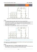
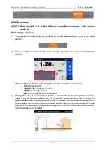
Used in IT, TT or other not connected earthing systems.
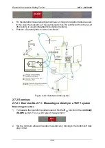
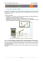
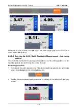
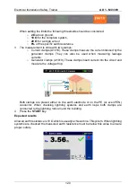
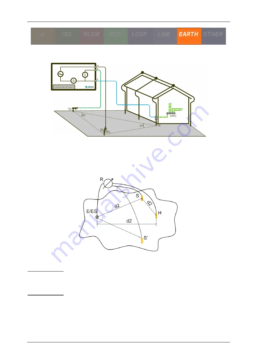
Figure 2-54: Three-wire test, two probes, and equilateral placement of probes
Functionality and placing of test probes
For a standard earthing resistance two test probes (voltage and current) are used.
Because of the voltage funnel it is important that the test electrodes are placed correctly.
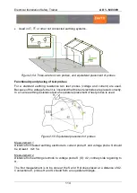
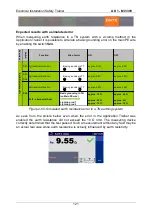
In a 3-wire earthing resistance test an equilateral placement of test probes is used.
Figure 2-55: Equilateral placement of probes
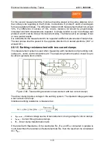
Measurement 1
Distance from tested earthing electrode to current probe H and voltage probe S should
be at least: d2= 5∙a
Measurement 2
Distance from earthing electrode to voltage probe S (S’): d2, contrary side regarding to
H.
The first measurement is
to be done at the S and H probes placed at a distance of∙d2.
Connections E, probes H and S should form an equilateral triangle.
Содержание MI 3399
Страница 27: ...Electrical Installation Safety Trainer AD 1 MI 3399 27...
Страница 28: ...Electrical Installation Safety Trainer AD 1 MI 3399 28 AD 1 MI 3399 EIS Electrical Installation Safety Trainer...
Страница 46: ...Electrical Installation Safety Trainer AD 1 MI 3399 46 3 Exit settings...
Страница 74: ...Electrical Installation Safety Trainer AD 1 MI 3399 74...
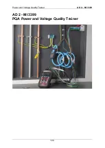
Страница 122: ...Power and Voltage Quality Trainer AD 2 MI 3399 122 AD 2 MI 3399 PQA Power and Voltage Quality Trainer...
Страница 197: ...Power and Voltage Quality Trainer AD 2 MI 3399 197 Figure 4 89 Transient Chart view...
Страница 204: ...PAT Appliances Machines Safety Trainer AD 3 MI 3399 204...
Страница 205: ...PAT Appliances Machines Safety Trainer AD 3 MI 3399 205 AD 3 MI 3399 PAT Appliances Machines Safety Trainer...
Страница 249: ...PV Photovoltaic Systems Trainer AD 4 MI 3399 249...
Страница 250: ...PV Photovoltaic Systems Trainer AD 4 MI 3399 250 AD 4 MI 3399 PV Photovoltaic Systems Trainer...

