Power and Voltage Quality Trainer
AD 2
– MI 3399
136
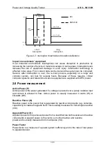
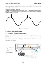
Figure 3-1: 3-phase 4-wire electrical system
In order to “simulate” this connection, in the Application Trainer, the instrument and
current clamps should be connected to the Application Trainer as shown in the figure
below.
Instrument
N
L1
L2
L3
GN
D
N
I1
I2
I3
IN
I1
I2
I3
IN
1
2
GND/N
3
Training corner
Figure 3-2: 3-phase 4-wire system connection to the Application Trainer
3.2 Instrument Setup
In order to measure power parameters correctly it is essential to properly setup the
instrument.
Procedure how to do this is described in the next few figures. First, go to the
MEASUREMENT SETUP menu and select the CONNECTION SETUP submenu.
CONNECTION MENU is shown in the figure below.
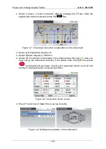
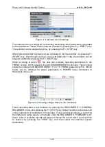
Figure 3-3: Connection setup menu
1.
Select Nominal voltage L-N and press the
key
2.
Set nominal voltage and ratio as shown in the figure below
ENTER
Содержание MI 3399
Страница 27: ...Electrical Installation Safety Trainer AD 1 MI 3399 27...
Страница 28: ...Electrical Installation Safety Trainer AD 1 MI 3399 28 AD 1 MI 3399 EIS Electrical Installation Safety Trainer...
Страница 46: ...Electrical Installation Safety Trainer AD 1 MI 3399 46 3 Exit settings...
Страница 74: ...Electrical Installation Safety Trainer AD 1 MI 3399 74...
Страница 122: ...Power and Voltage Quality Trainer AD 2 MI 3399 122 AD 2 MI 3399 PQA Power and Voltage Quality Trainer...
Страница 197: ...Power and Voltage Quality Trainer AD 2 MI 3399 197 Figure 4 89 Transient Chart view...
Страница 204: ...PAT Appliances Machines Safety Trainer AD 3 MI 3399 204...
Страница 205: ...PAT Appliances Machines Safety Trainer AD 3 MI 3399 205 AD 3 MI 3399 PAT Appliances Machines Safety Trainer...
Страница 249: ...PV Photovoltaic Systems Trainer AD 4 MI 3399 249...
Страница 250: ...PV Photovoltaic Systems Trainer AD 4 MI 3399 250 AD 4 MI 3399 PV Photovoltaic Systems Trainer...

