Power and Voltage Quality Trainer
AD 2
– MI 3399
149
Load type: Inductive
Load character: Load (Consumption of electrical power)
Frequency: 50/60 Hz
138
V deep, 5 period’s long voltage dip is present on phase L1. The dip is
repeated every 10 seconds.
4.2.1 Instrument setup for Dip capturing
The Power Master MI 2892 should be connected to the Application Trainer and set up
as described in section 3.2 Instrument Setup. It is good practice to verify the
Connection Check status in the MEASRUEMENT SETUP
CONNECTION SETUP
menu. If it is marked with an OK sign ( ), it means that the instrument is connected
properly.
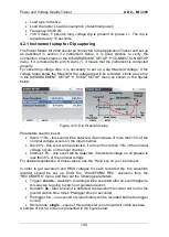
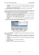
For observing voltage dips, it is necessary to set up a dip threshold voltage. If the
voltage drops below the threshold, the voltage dip will be recorded. Limits are set up
in the MEASRUEMENT SETUP
EVENT SETUP menu as shown in the figures
below.
Figure 4-10: Dip threshold setup
Parameters need to be set:
Swell: 110% - this event will be detected, if an increase of more than 10% of the
nominal voltage occurs on the input channel,
Dip: 90% - this event will be detected, if a drop of more than 10% of the nominal
voltage occurs on the input channel,
Interrupt: 5% - this event will be detected, if detected voltage on all phases is
less than 5% of the nominal voltage.
For detailed explanation of these values, use the
“Help” key on your instrument.
In order to get waveform and RMS voltages for each recorded dip, the waveform
recorder should be set up. Enter the
“WAVEFORM REC.” submenu from the
“RECORDERS” menu, and then set the following parameters:
Trigger:
events
– waveform recording will be executed after an event happens,
this way we’re going to catch our generated event,
Duration:
2s
- after an event is detected, the waveform recorder will run for the
given Duration time minus Pretrigger time (in seconds),
Pretrigger:
1s
– one second of signal history will be recorded before the trigger
occurs,
Store mode:
single
– value of this parameter is not important in this exercise.
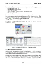
A sample of such a screen is presented in the figure below.
Содержание MI 3399
Страница 27: ...Electrical Installation Safety Trainer AD 1 MI 3399 27...
Страница 28: ...Electrical Installation Safety Trainer AD 1 MI 3399 28 AD 1 MI 3399 EIS Electrical Installation Safety Trainer...
Страница 46: ...Electrical Installation Safety Trainer AD 1 MI 3399 46 3 Exit settings...
Страница 74: ...Electrical Installation Safety Trainer AD 1 MI 3399 74...
Страница 122: ...Power and Voltage Quality Trainer AD 2 MI 3399 122 AD 2 MI 3399 PQA Power and Voltage Quality Trainer...
Страница 197: ...Power and Voltage Quality Trainer AD 2 MI 3399 197 Figure 4 89 Transient Chart view...
Страница 204: ...PAT Appliances Machines Safety Trainer AD 3 MI 3399 204...
Страница 205: ...PAT Appliances Machines Safety Trainer AD 3 MI 3399 205 AD 3 MI 3399 PAT Appliances Machines Safety Trainer...
Страница 249: ...PV Photovoltaic Systems Trainer AD 4 MI 3399 249...
Страница 250: ...PV Photovoltaic Systems Trainer AD 4 MI 3399 250 AD 4 MI 3399 PV Photovoltaic Systems Trainer...

