background image


Electrical Safety and Quality  

Application Trainer  

MI 3399


Instruction manual with exercises


Version 1.1.2 Code No. 20 752 492 

Source document version: 1.1, Code no. 20 752 492 
 

Содержание MI 3399

Страница 1: ...Electrical Safety and Quality Application Trainer MI 3399 Instruction manual with exercises Version 1 1 2 Code No 20 752 492 Source document version 1 1 Code no 20 752 492...

Страница 2: ...ttp www metrel si E mail metrel metrel si 2015 METREL Electrical power installations testing and verifications Miha Doberlet METREL 2015 No part of this publication may be reproduced or utilized in an...

Страница 3: ...4 AD 1 MI 3399 EIS Electrical Installation Safety Trainer 28 AD 2 MI 3399 PQA Power and Voltage Quality Trainer 122 AD 3 MI 3399 PAT Appliances Machines Safety Trainer 205 AD 4 MI 3399 PV Photovoltaic...

Страница 4: ...Trainer 8 2 4 AD4 MI 3399 PV Photovoltaic Systems Trainer 9 3 Unpacking of Application trainer 10 4 Description of the MI 3399 Application Trainer 15 4 1 Technical data 15 4 2 Connection to mains volt...

Страница 5: ...king the Application trainer 10 13 Figure 3 11 Unpacking the Application trainer 11 14 Figure 3 12 Unpacking the Application trainer 12 14 Figure 3 13 Unpacking the Application trainer 13 14 Figure 4...

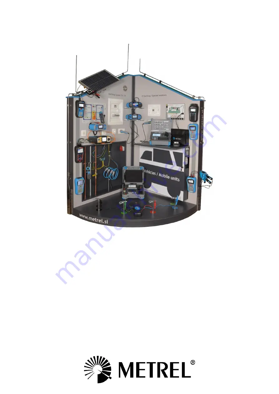
Страница 6: ...ation It is aimed as well to be used at sale demonstration rooms for presentation of electro installation testers and their application The MI 3399 is foldable for simplified transport The MI 3399 is...

Страница 7: ...amp TRMS with Power Harmonics A 1018 Current Clamp low range leakage A 1019 Current Clamp S 2009 Test lead set 2m 4pcs 25 pcs Guide for testing and verification of low voltage installations 25 pcs Gui...

Страница 8: ...Analyser 25 pcs Guide for modern Power Quality Analysing Techniques 25 pcs Chart Power Quality Analysing and troubleshooting procedures Power Quality Simulator Package Set enables performing of the fo...

Страница 9: ...s I washing machine Low voltage switchgear Electrical machine IEC cord 2 4 AD4 MI 3399 PV Photovoltaic Systems Trainer This module comes together with the following equipment MI 3109 PS EurotestPV Pro...

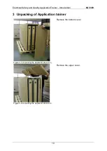
Страница 10: ...ality ApplicationTrainer Introduction MI 3399 10 3 Unpacking of Application trainer Remove the bottom cover Figure 3 1 Unpacking the Application trainer 1 Remove the upper cover Figure 3 2 Unpacking t...

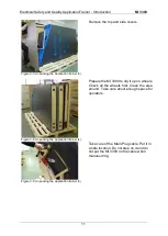
Страница 11: ...e the MI 3399 to dig it up on wheels Check all the wheels first Clean the area around Take care about enough space for operators Figure 3 4 Unpacking the Application trainer 4 Take care of the Main Pl...

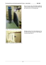
Страница 12: ...3399 Additional help is needed to protect the MI 3399 during this step to put it on wheels gently Figure 3 6 Unpacking the Application trainer 6 Remove screws from the backside of the MI 3399 Save th...

Страница 13: ...king the Application trainer 8 Prepare the bottom part Find two wires below the cover Connect the blue and black banana to the blue and black plugs on the bottom side of the MI3399 Fit the corner s bo...

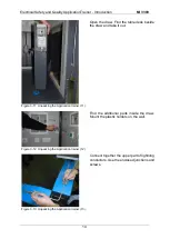
Страница 14: ...e it out Figure 3 11 Unpacking the Application trainer 11 Find the additional parts inside the draw Mount the plastic holders on the wall Figure 3 12 Unpacking the Application trainer 12 Connect toget...

Страница 15: ...are no damages noticed at the outlet mechanical damages broken contacts etc That there are no damages present at the board s plug and at the board itself damaged outlets mechanical damages of other e...

Страница 16: ...d not through electronic circuits Do not short accessible contacts at one phase or three phase outlets 4 2 1 Connection to a 1 phase outlet Figure 4 1 Connection of the Application Trainer to one phas...

Страница 17: ...and PE conductors to ensure that correct pins on the plug are connected to the correct conductors L to L N to N PE to PE The circuit decides this based on the measured voltage between N and PE points...

Страница 18: ...and PE are also switched Before any radical changes are made on the socket first check if the circuit breaker at the bottom of the error switch box is switched on If not turn it on and check the ligh...

Страница 19: ...Electrical Safety and Quality ApplicationTrainer Introduction MI 3399 19 4 4 Basic parts of the Application Trainer Figure 4 4 Parts of the Application Trainer explained...

Страница 20: ...ower analysis module 1 Portable appliance testing PAT module 2 Photovoltaics module 3 Error switch panel 4 with Error switches S1 S33 Circuit breaker dubbing as an ON OFF switch TN TT switch A very im...

Страница 21: ...Electrical Safety and Quality ApplicationTrainer Introduction MI 3399 21 Figure 4 5 Location of RCDs fuses circuit breakers sockets and switches...

Страница 22: ...t for supplying different loads F 1 4 Light Circuit UTP LAN sockets for testing communication network parameters errors faults and distances to the faults and crosstalk N PE TN TT Open Short switch to...

Страница 23: ...periods long each 10 seconds S4 Capacitive load energy capacitive switching nonlinear S5 Harmonics Voltage harmonics 3rd harmonic 5 5th harmonic 5 7th harmonic 5 Current harmonics 3rd harmonic 15 5th...

Страница 24: ...rox 3 3 1 S18 R LOW TN TT F1 4 PE light 20 1 S19 R LOW Z LOOP TN TT F1 2 PE outlet 3 ph approx 3 4 1 S20 R LOW Z LOOP TN TT F2 2 PE outlet 2 3 2 S21 R LOW MPE PE Gas approx 2 2 1 S22 R LOW MPE PE Heat...

Страница 25: ...sulation 500 V DC 20 M 20 M Leakage 230 V 50 Hz 2 12 mA 0 00 mA Subleakage 2 12 mA 0 00 mA Insulation fault Error value 238 k 20 M Insulation 500 V DC 0 238 M 20 M Touch Leakage 230 V 0 97 mA 0 00 mA...

Страница 26: ...d on petrol Do not spill cleaning liquid over the Application trainer 5 2 Service In case of any board malfunction or if there is any damage noticed at the board the board must be serviced by a compet...

Страница 27: ...Electrical Installation Safety Trainer AD 1 MI 3399 27...

Страница 28: ...Electrical Installation Safety Trainer AD 1 MI 3399 28 AD 1 MI 3399 EIS Electrical Installation Safety Trainer...

Страница 29: ...ircuit line neutral impedance and prospective short circuit current 49 2 2 2 2 Short circuit line line impedance and prospective short circuit current 50 2 2 2 3 Voltage drop 51 2 2 3 Exercises 52 2 2...

Страница 30: ...time current and contact voltage measurements in an IT earthing system 81 Measuring procedure 81 Expected results 82 2 5 Insulation monitor devices and measuring single fault leakage currents 84 2 5...

Страница 31: ...obes 111 2 8 1 4 3 wire earthing resistance test internal generator two probes 112 Functionality and placing of test probes 114 2 8 1 5 Earthing resistance test with two current clamps 115 2 8 2 Exerc...

Страница 32: ...ance measurements TT system 75 Figure 2 24 RCD measurement in Application Trainer s switchboard with cables on the supply side 75 Figure 2 25 RCD measurement in the Application Trainer with the schuko...

Страница 33: ...Equilateral placement of probes 114 Figure 2 56 Total earthing resistance measurement with two current clamps 115 Figure 2 57 Test system individual earthing rods with two current clamps 116 Figure 2...

Страница 34: ...evice used 1 1 TN system A TN system is earthed at the power source and or distribution points Exposed conductive parts are connected earthed to the points via the PE or PEN conductor PEN conductor se...

Страница 35: ...upplying system The PEN conductor is used for protection purposes and is carrying load currents All line conductors are fuse protected The earthing resistance is usually low enough because of low PEN...

Страница 36: ...rmer ZNeutral conductor ZLocal neutral conductor Loop impedance in a TN system ZLoop ZLine conductor ZTransformer ZNeutral conductor ZLocal PE conductor In case the continuity is good for all conducto...

Страница 37: ...onductor Line Impedance in TT system is much lower than Loop Impedance because of the fault loop current flowing through the ground 1 3 IT system The IT system has the supply part of the power source...

Страница 38: ...lf Ships Computer power supply systems Chemical industry Mining industry Explosive atmospheres chemical industry2 The main advantage is that in case of the first fault between phase and earth the syst...

Страница 39: ...ce within prescribed time interval in case of faulty load After pressing the START key the instrument loads the installation between L and PE terminals see Figure 1 7 and measures loaded Figure 1 7 sw...

Страница 40: ...limit next possible solutions are recommended Tracing of possible bad contacts in the tested mains socket Tracing of possible bad contacts in lines L and PE from the fuse box to the mains socket Chan...

Страница 41: ...rotection device A Type of automatic Fuse B Type of automatic Fuse C Type of Fuse gG Ia 5 In A Zs 0 2s Ia 5 In A Zs 0 2s Ia A Zs 0 4s 2 10 22 20 11 16 13 7 4 20 11 40 5 5 32 6 8 6 30 7 3 60 3 65 47 4...

Страница 42: ...ble 1 3 Trip out times according to IEC 60364 4 41 1 4 4 2 RCD trip out current test With the trip out current test the correct operation of the RCD is verified Conditions Successful trip out Current...

Страница 43: ...wiring are not protected In this case the limit for over current protection must be considered A typical example is a socket with integrated RCD If a RCD device is not present then the selected limit...

Страница 44: ...voltage and the test voltage must be higher than 500V The value of the insulation resistance must be higher than 1 M 1 4 7 Continuity The basic protection against electroshock of hazardous voltage is...

Страница 45: ...lows 1 Continuity testing RLOW 2 Insulations resistance RISO 3 Line impedance ZLINE 4 Fault loop impedance ZLOOP 5 RCD testing 6 Earth resistance testing 7 IMD and ISFL testing 8 Voltage testing 2 1 I...

Страница 46: ...Electrical Installation Safety Trainer AD 1 MI 3399 46 3 Exit settings...

Страница 47: ...tem Scope of the line impedance test is To verify effectiveness of installed over current disconnection devices To verify internal impedance for supplying purpose To verify too high excessive internal...

Страница 48: ...s the resistive and inductive part in the short circuit loop The main part of inductivity comes from the power transformers inductances The resistance part mainly comes from copper wiring in the loop...

Страница 49: ...currents In this case the contribution of the inductive part is relatively high 2 2 2 1 Short circuit line neutral impedance and prospective short circuit current The line neutral short circuit loop c...

Страница 50: ...s and resistances that forms the line line loop In a three phase system there are three line line impedances ZL1 L2 ZL1 L3 and ZL2 L3 ZLINE ZLx Ly ZLx ZLy ZTLL The prospective short circuit current IP...

Страница 51: ...the circuit the fuse installed before that circuit is considered The difference between both measurements must not be greater than 3 After the reference impedance ZREF has been determined the actual v...

Страница 52: ...ine which measures impedance between phase and neutral conductors The line impedance measured at the supply side is actually the reference line impedance ZREF To measure the voltage drop select the vo...

Страница 53: ...changed the prospective short circuit current IPSC limit is set automatically 3 If a schuko commander is to be used plug the commander into the appropriate outlet If the cables are used connect all c...

Страница 54: ...ase TN TT system is used a 6A B type fuse with 200ms trip out time is used In this case the allowed impedance is 7 3 As is seen from the screens above the impedance voltage drop and IPSC are within li...

Страница 55: ...h measures impedance between phase and neutral conductors The line impedance measured at the supply side is actually the reference line impedance ZREF To measure the voltage drop select the voltage dr...

Страница 56: ...never a fuse parameter setting is changed the prospective fault current IPSC limit is set automatically 4 If the commander is to be used plug the commander into the appropriate schuko outlet If the co...

Страница 57: ...n from the screens above the impedance voltage drop and IPSC are within limits and the test is marked as passed Expected results with a simulated error During the test we add an error in the circuit i...

Страница 58: ...rthed through a sufficient high impedance at the source The line impedance depends on the size of the system and size of the transformer used A small system requires a smaller transformer which result...

Страница 59: ...nce line impedance should be done only on the one socket outlet which is selected as the reference one All subsequent voltage drop measurements are then based on that reference line impedance 2 To mea...

Страница 60: ...use settings should be set 4 Whenever a fuse parameter setting is changed the prospective fault current IPSC limit is set automatically 5 If the commander is to be used plug the commander into the app...

Страница 61: ...tion Safety Trainer AD 1 MI 3399 61 Since no faults in the IT system were present all tests passed Expected results with a simulated error It is not possible to simulate errors in an IT system in the...

Страница 62: ...ffectiveness of installed over current and or residual current disconnection devices To verify fault loop impedances prospective fault currents and fault voltage values Figure 2 10 Chart reference for...

Страница 63: ...impedance 0 4 In applications where the measurement is carried out in close proximity to the power transformer 50m the inductivity can be of a similar value than the resistance part In this case it i...

Страница 64: ...nstalled protection device will disconnect the fault loop within the prescribed time interval Limit values for IPFC and ZL PE depend on selected fuse type size and required trip out time Figure 2 14 F...

Страница 65: ...2 3 1 3 Fault loop fault impedance and prospective fault current in RCD protected TN and TT systems In TT and TN systems where RCD is used a different function for measuring the fault loop impedance i...

Страница 66: ...witch on off events on the mains To solve this problem advanced measuring techniques must be used that are beyond the scope of this test Figure 2 16 Loop impedance measurement in a RCD protected syste...

Страница 67: ...t is done on the supply side as is the case of this exercise 2 To get correct readings during measurement select the appropriate fuse settings fuse type size and trip out time by clicking in the botto...

Страница 68: ...function should be used in order not to trip the RCD The prospective fault current IPSC is calculated as where UN nominal value determined according to the measured voltage UL PE The measured ZLOOP p...

Страница 69: ...hich is approximately 3 Expected results with a simulated error It is not possible to simulate an error in the Application Trainer on the supply side 2 3 2 2 Exercise No 2 3 2 ZL PE and IPFC measureme...

Страница 70: ...ment is the ZS RCD function which will not trip the RCD Measuring procedure 1 Select the fault loop impedance measurement ZS RCD for a RCD protected system that measures impedance between phase and ea...

Страница 71: ...ver a fuse parameter setting is changed the prospective fault current IPSC limit is set automatically 3 If a schuko commander is to be used plug the commander into the appropriate outlet If the cables...

Страница 72: ...he PE conductor by enabling switch S20 in the Application Trainer Toggling this switch introduces additional resistance on the PE conductor on a 1 phase TN earthing system Figure 2 20 Simulated error...

Страница 73: ...uce an additional 10 to the wiring on the line conductor This is done by enabling switches S12 3 phase S13 1 phase or S14 1 phase in the Application Trainer Figure 2 21 Simulated errors on the line co...

Страница 74: ...Electrical Installation Safety Trainer AD 1 MI 3399 74...

Страница 75: ...n the installation Even relatively small currents are dangerous if resistance to earth and equipotential bonding are relatively high Typical fault reasons are deteriorated insulation dirt moisture fil...

Страница 76: ...re 2 26 RCD measurement in an IT earthing system 2 4 1 1 Function of RCD In TN systems fault and leakage currents flow from live conductors to protection earth conductor and then through PEN conductor...

Страница 77: ...the fault to protection earth conductor PE and then to ground via the system s earthing resistance The current is driven to the grounding system of the power transformer and thus to the neutral termin...

Страница 78: ...ology Figure 2 27 RCD measurement in a 1 phase TT system Measuring procedure 1 To measure the contact voltage UC of a TT system select the RCD UC test 2 To measure the trip out time t N of a TT system...

Страница 79: ...ximity That is why the contact voltage limit may be set to 50 V 6 If a schuko commander is to be used plug the commander into the appropriate outlet If the cables are used connect all cables appropria...

Страница 80: ...tripped as is the intention of both test Be sure to reset the RCD before each test Instead all three mentioned test a predefined RCD AUTO SEQUENCE test RCD Auto can be used The functionality is that i...

Страница 81: ...m select the RCD t test 3 To measure the trip out current I of a IT system select the RCD I test 4 To perform all RCD measurements UC t N I in one easy step select the RCD Auto test 5 Set the RCD test...

Страница 82: ...nd Line2 of the first circuit Then connect the PE cable green cable in Figure 2 26 to one of the Line conductors on the second circuit as shown in Figure 2 26 7 Press the START key Expected results In...

Страница 83: ...intention of both tests Be sure to reset the RCD before each test Instead of performing all three mentioned tests individually a predefined RCD AUTO SEQUENCE test RCD Auto can be used The auto test p...

Страница 84: ...gure 2 29 Measuring ISFL and IMD in an IT system 2 5 1 1 Single fault leakage current ISFL ISFL is used for evaluating the effectiveness of an IT earthing systems that converts to a TT system during a...

Страница 85: ...MD IMDs and other monitoring devices usually include a self test option for an alarm circuit The alarm circuit can be double checked by applying an adjustable resistor between line and PE conductors W...

Страница 86: ...Press the START key Expected results In a normal situation when no faults are present the measured single fault leakage current should be well below the defined limit 3 5 mA as seen in the picture be...

Страница 87: ...PE outlet 20 1 S16 ISFL IMD IT F3 2 ISFL approx 6 mA 230 V approx 3 mA 115 V 1 3 mA S17 R LOW IT PE ref approx 3 3 1 S18 R LOW TN TT F1 4 PE light 20 1 S19 R LOW Z LOOP TN TT F1 2 PE outlet 3 ph appr...

Страница 88: ...f the cables are used connect all cables appropriately the PE cable to the PE conductor the N cable to Line2 and the L cable to Line1 4 Press the START key Expected results In a normal situation the I...

Страница 89: ...est shows no difference in measurement To turn on the PE error enable switch S15 in the Application Trainer To simulate the ISFL fault on IMD device enable switch S16 Figure 2 31 IMD simulated errors...

Страница 90: ...ion Safety Trainer AD 1 MI 3399 90 2 6 Insulation resistance measurement Figure 2 32 Chart reference for insulation resistance measurements Figure 2 33 Insulation resistance measurement at the switchb...

Страница 91: ...Insulation resistance M SELV and PELV 250 0 5 Installations with nominal voltages up to and including 500 V including FELV 500 1 0 Above 500 V 1000 1 0 Table 2 2 Insulation resistance limits Capacita...

Страница 92: ...circuit breakers removing fuses 2 6 1 1 Insulation resistance of individual circuits items Especially during troubleshooting insulation resistance of individual installation parts are checked In this...

Страница 93: ...ppropriate outlet If the cables are used connect all cables appropriately the PE cable to the PE conductor the N cable to Line2 and the L cable to Line1 During the measurement check the insulation res...

Страница 94: ...be checked 2 6 2 2 Exercise No 2 6 2 RISO in a 3 phase TN TT system on the supply side Measuring procedure 1 To measure the insulation resistance select first the RISO function in the ISO section Exer...

Страница 95: ...Line1 During the measurement check the insulation resistance between all conductors LX LY L N L PE N PE 4 Press the START key Expected results Conduct this measurement at the switchboard After disabli...

Страница 96: ...at show a fault in the circuit simply by disabling all subsequent fuses and RCDs in our measuring subsystem The fuse RCD that remains with the fault is the circuit that has the fault As seen from the...

Страница 97: ...If a schuko commander is to be used plug the commander into the appropriate outlet If the cables are used connect all cables appropriately the PE cable to the PE conductor the N cable to Line2 and the...

Страница 98: ...insulation resistance is much lower than required This tells us the wiring should be checked Exercises Switch Function Site of error ON OFF S27 RISO IT F3 1 L1 L2 outlet approx 0 45 M 200 M S28 ISFL...

Страница 99: ...RISO function in the ISO section 2 Set the minimum allowed insulation resistance by clicking in the bottom left dark grey corner 3 During this test only cables may be used where the PE and N cable ar...

Страница 100: ...ing its function in a building that has gas pipes installed At low voltage a varistor has a high electrical resistance and the current flows normally over the gas pipe In case of overcurrent e g light...

Страница 101: ...sulation fault caused the measured insulation resistance is much lower than required This tells us the wiring should be checked Exercises Switch Function Site of error ON OFF S27 RISO IT F3 1 L1 L2 ou...

Страница 102: ...ctrical Installation Safety Trainer AD 1 MI 3399 102 2 7 Conductor continuity measurement Figure 2 41 Chart reference for continuity measurements Figure 2 42 Continuity measurement between MPE and soc...

Страница 103: ...accordance with conductor s length and cross section l A RCON Conductor s resistance Specific resistance of conductor s material for Cu 0 0172 mm2 m l Length of conductor m A Cross section of conduct...

Страница 104: ...grated in installation testers Problem of parallel paths must be considered Figure 2 44 Standard continuity test 2 7 2 Exercises 2 7 2 1 Exercise No 2 7 1 Measuring continuity in a TN TT system Measur...

Страница 105: ...cture above 3 During this type of measurement only the cables may be used Connect the PE a neutral cables together to create a PEN cable and place it on a reference point somewhere in the building e g...

Страница 106: ...y error In a TN system the simulated error introduced additional resistance of 3 4 Since the limit for systems with installed RCD is 2 the test failed The device correctly interpreted the result Exerc...

Страница 107: ...rement only the shuko commander is used Plug the commander into the chosen outlet Here the resistance between neutral and PE conductors is measured 4 Press the START key Expected results Depending on...

Страница 108: ...est in order for the device to correctly interpret the results Expected results with a simulated error A typical fault when measuring continuity would be if the resistance of PE conductor would be abo...

Страница 109: ...Electrical Installation Safety Trainer AD 1 MI 3399 109 In this case we simulated an error which introduced an additional resistance of 3 4 in a TN system The test failed as expected...

Страница 110: ...99 110 2 8 Earth resistance measurements Figure 2 47 Chart reference for earth resistance measurements Figure 2 48 Earth resistance measurement using the 3 wire method Figure 2 49 Earth resistance mea...

Страница 111: ...resistances are usually very low below 1 TT installations have their own main earthing The resistances are usually higher than in TN systems from few up to several hundred Because of this dangerous f...

Страница 112: ...urban areas if there is no appropriate place for test probes Applicable in areas where different local earthings are connected together making the local earthing system very large Figure 2 51 Two wir...

Страница 113: ...individual earthing resistances the measured rod point must be disconnected from the system In TN systems incoming PE PEN conductor must be disconnected Figure 2 53 Selective earthing measurement stan...

Страница 114: ...ant that the test electrodes are placed correctly In a 3 wire earthing resistance test an equilateral placement of test probes is used Figure 2 55 Equilateral placement of probes Measurement 1 Distanc...

Страница 115: ...opposite direction from tested electrode 180 or at least 90 2 8 1 5 Earthing resistance test with two current clamps This measurement system is used when measuring earth resistances of grounding rods...

Страница 116: ...2 57 Applicable for measuring earthing resistance in TN earthing systems Figure 2 58 Especially suitable in urban area No disconnection of measured electrodes Very fast measurement no need to place m...

Страница 117: ...ng thresholds should be considered o 2 above ground o 10 for the complete system o 20 for a single wire or o 8 of the specific earth resistance 3 During this type of measurement cables in combination...

Страница 118: ...nnected transformer Expected results with a simulated error When measuring earth resistance in a TT system with a 3 wire method in the Application Trainer it is possible to simulate grounding errors S...

Страница 119: ...ent two clamp method This method is intended for measuring earth resistance in a TN earthing systems or when lightning systems and earth loops have to be checked Measuring procedure 1 To measure the e...

Страница 120: ...also be used when measuring leakage currents o Generator clamps A1019 These clamps insert current into the circuit and measure the voltage drop Both clamps are placed either on the earth electrode or...

Страница 121: ...esistance did not exceed the 10 limit The measuring device correctly determined that the test passed Such a measurement without any fault may be an actual real case since earth resistance is actually...

Страница 122: ...Power and Voltage Quality Trainer AD 2 MI 3399 122 AD 2 MI 3399 PQA Power and Voltage Quality Trainer...

Страница 123: ...140 4 Exercises 143 4 1 Exercise 1 Basic general manipulation and recording 143 4 1 1 Real time measurements 144 4 1 2 Recording measurements 144 4 1 3 Downloading and observing recorded data in Power...

Страница 124: ...hreshold and duration definitions 131 Figure 2 4 voltage fluctuation 134 Figure 2 5 transients 135 Figure 3 1 3 phase 4 wire electrical system 136 Figure 3 2 3 phase 4 wire system connection to the Ap...

Страница 125: ...4 33 Waveform record screen 164 Figure 4 34 General recorder setup 165 Figure 4 35 Event table interrupts 165 Figure 4 36 Voltage interrupt RMS measurements and waveform shape 165 Figure 4 37 Generate...

Страница 126: ...ush 188 Figure 4 78 Observing current waveform during inrush capturing 189 Figure 4 79 Real time measurements of current inrush 189 Figure 4 80 Download dialog 190 Figure 4 81 Inrush record informatio...

Страница 127: ...cument describes 12 exercises They are organized from the easiest describing most common measuring practice to more complex and practical Each exercise will lead you step by step from instruments setu...

Страница 128: ...considered as a measurement of low frequency conducted disturbance with the addition of transient phenomena The following parameters of supply voltage are influenced by disturbances frequency voltage...

Страница 129: ...a dip Origin Voltage dips are caused by failures in the network or by excessively large inrush currents Impact on customers equipment Studies conducted over recent years have confirmed that voltage d...

Страница 130: ...ltage The duration of an interruption is measured in the same manner as a measurement of dip duration after setting an interruption threshold Because of the measurement technique a short circuit fault...

Страница 131: ...t for several hours Because of these reasons critical computer systems and telecommunication equipment are supplied with UPS power 2 6 Power measurement Active Power P Active power is the power genera...

Страница 132: ...ly odd harmonics can be detected with a measurement instrument If the load is non symmetrically controlled positive and negative half periods of current differ in shape and rms value causing even harm...

Страница 133: ...angles between consecutive phases are not equal Term imbalance is also used as an alternative Supply voltage unbalance is defined as the ratio of the negative sequence component to the positive seque...

Страница 134: ...red as annoying 2 11 Inrush Current needed to start a motor can be 10 to 15 times the normal operating current This initial surge of current can cause dips in voltage and can be hard to analyse with n...

Страница 135: ...n lead to faulty operation Electronic drives may fall out impulse transient impulse transient oscillatory transient Figure 2 5 transients 3 Connection and setup 3 1 Electrical system configuration Bef...

Страница 136: ...raining corner Figure 3 2 3 phase 4 wire system connection to the Application Trainer 3 2 Instrument Setup In order to measure power parameters correctly it is essential to properly setup the instrume...

Страница 137: ...ect Phase Current Clamps menu and press the key 5 Select A1033 Clamps and press the key Figure 3 5 Current clamp selection 6 Select 100 measuring range and press the key Figure 3 6 Setting Current cla...

Страница 138: ...nnel U1 11 Select System frequency 50 60 Hz 12 Check the Connection check status If it s marked with a OK sign then you have set up the instrument correctly If the status mark is fail then press and d...

Страница 139: ...current flow from supply to load I 1 2 If a clamp on current transformer is connected in reverse the measured power in that phase would normally appear negative Phase relationships The clamp on curre...

Страница 140: ...gger Waveform recorder is active recording in progress Transient recorder is active waiting for trigger Transient recorder is active recording in progress Memory list recall Shown screen is recalled f...

Страница 141: ...it to the PC with a USB cable 3 Windows will install all necessary drivers automatically Note that the Windows user needs Administrator s privileges to complete this task 4 In the Instrument go to the...

Страница 142: ...w PC Side 7 For a quick check it is advisable to click on the Real time Scope icon and see if instantaneous measurements are downloaded from the instrument and presented on the screen Figure 3 13 Obse...

Страница 143: ...n PowerView Before start set switches S1 S11 of the Application Trainer to OFF as shown in the table below Attention Please note that only one 1 error switch may be turned ON at any time when simulati...

Страница 144: ...tart observing measurements 4 1 1 Real time measurements By entering the MEASUREMENTS MENU the user can observe measured parameters in real time Figure 4 1 Measurement submenu Figure 4 2 Real time mea...

Страница 145: ...rding parameters in the TREND screen which appears in each MEASUREMENTS submenu Figure below shows the voltage trend MEASUREMENT U I f TREND press 2x key F4 Similar trends can be obtained for power pa...

Страница 146: ...and setup Open PowerView and click on the Download button from your toolbar A new window will appear Your instrument s information should be available on top of the window and a list of available rec...

Страница 147: ...I f option then double click Current Next tick I1 option New tabs Trend chart only when general recording option is used and Table will appear on right side Trend chart see Figure 4 8 Chart view grap...

Страница 148: ...d Max presents maximal 10 12 cycle RMS value in given time interval Other data power harmonics etc can be accessed and analysed in similar fashion 4 2 Exercise 2 Voltage Dip In this exercise we will s...

Страница 149: ...t Swell 110 this event will be detected if an increase of more than 10 of the nominal voltage occurs on the input channel Dip 90 this event will be detected if a drop of more than 10 of the nominal vo...

Страница 150: ...e alarms Off no alarms will be triggered Start time Manual Duration 1 days recording will stop after 24 hours Figure 4 12 General recorder setup The instrument is now prepared for voltage event record...

Страница 151: ...ts the recorder can be stopped by pressing the F1 STOP key in the RECORDER GENREAL REC menu To transfer the record into PowerView we first need to be sure that PowerView is set up as described in sect...

Страница 152: ...types appear in the Data explorer tab Triggered Waveform Snapshot provides voltage and current samples for a captured voltage event in our case a 5 periods long dip Inrush Logging provides voltage an...

Страница 153: ...voltage dip can be observed in table form within General Logging where only dip signatures are shown This kind of dip presentation is mainly used for statistic evaluation for example how many dips occ...

Страница 154: ...n timeline graph in PowerView Each dip can be analysed in depth through waveform records PowerView can show two waveform record logs Inrush log and waveform snapshot Inrush log represents RMS values o...

Страница 155: ...Captured voltage dip RMS values For further analysis the user can observe the waveform shape of the dip From this graph dip phase shift and dip starting point on the wave can be seen Figure below repr...

Страница 156: ...swell is present on phase L1 The swell is repeated every 10 seconds 4 3 1 Instrument setup for Swell capturing The Power Master MI 2892 should be connected to the Application Trainer and set up as de...

Страница 157: ...Store mode single value of this parameter is not important for this exercise A sample of such a screen is presented in the figure below Figure 4 22 Waveform record screen Now go to RECORDERS GENERAL...

Страница 158: ...erving swells on the instrument Enter the RECORDERS EVENTS TABLE menu and check recorded events The events table should be similar as shown in the figure below Figure 4 24 Event table swells Additiona...

Страница 159: ...seen in the figure below Triggered waveform Event waveform is stored in this file type Each event is stored in a separate record General logging Data trends and event tables are stored in this file t...

Страница 160: ...tage swell can be observed in table form within General Logging where only swell signatures are shown This kind of swell presentation is mainly used for statistic evaluation for example how many swell...

Страница 161: ...d in timeline graph in PowerView Each swell can be analysed in depth through waveform records PowerView can show two waveform record logs Inrush log and waveform snapshot Inrush log represents RMS val...

Страница 162: ...d voltage swell RMS values For further analysis the user can observe also the waveform shape of the swell From this graph swell phase shift or swell starting point on the wave can be seen Figure below...

Страница 163: ...l power Frequency 50 60 Hz Voltage interrupt 5 periods long voltage interrupt is present on all phases The interrupt is repeated every 10 seconds 4 4 1 Instrument setup for Interrupt capturing The Pow...

Страница 164: ...nerated event Duration 2s after an event is detected the waveform recorder will run for the given Duration minus Pretrigger time in seconds Pretrigger 1s one second of signal history will be recorded...

Страница 165: ...interrupts on the instrument Enter the RECORDERS EVENTS TABLE menu and check recorded events The events table should be similar as shown in the figure below Figure 4 35 Event table interrupts Additio...

Страница 166: ...shown as seen in the figure below Triggered waveform Event waveform is stored in this file type Each event is stored in a separate record General logging Data trends and event tables are stored in th...

Страница 167: ...nterrupt can be observed in table form within General Logging where only interrupt signatures are shown This kind of interrupt presentation is mainly used for statistic evaluation for example how many...

Страница 168: ...d in timeline graph in PowerView Each interrupt can be analysed in depth through waveform records PowerView can show two waveform record logs Inrush log and waveform snapshot Inrush log represents RMS...

Страница 169: ...interrupt RMS values For further analysis the user can observe also the waveform shape of the interrupt From this graph interrupt phase shift or interrupt starting point on the wave can be seen Figure...

Страница 170: ...nonlinear load Recording and observing recorded data on the instrument Downloading and observing downloaded data in PowerView Before start please set the switches S1 S11 in the Application Trainer to...

Страница 171: ...d From the MAIN MENU enter the RECORDERS menu and then go to the GENRAL RECORDER menu Set up all parameters as shown in the figure below Figure 4 43 General record settings After these changes have be...

Страница 172: ...the existent state of the counters 2 Last integration period LAST mode measures energy during recording over the last completed interval It is calculated at the end of each interval 3 Current integra...

Страница 173: ...nto PowerView Obtained results for active power P fundamental reactive power Qfund and effective apparent power SEff are shown below Figure 4 47 Recorded power parameters presented in time chart in Po...

Страница 174: ...total consumed power is concentrated at the fundamental frequency as non fundamental harmonic power components are almost negligible However 15 phase shift between voltage and current introduce 178 kV...

Страница 175: ...Power and Voltage Quality Trainer AD 2 MI 3399 175 Figure 4 51 Real time measurement presented in table view in PowerView Figure 4 52 Phase diagram and unbalance presented in PowerView...

Страница 176: ...in the figure below Figure 4 54 Capacitive load on phase L1 On phase L2 a switching load is present which turns on and off every 10 seconds Rec interval n 1 Rec interval n 1 Rec interval n Time s Curr...

Страница 177: ...r on inductive load with 10 of third harmonics on current channel I3 Finish recording by entering the RECORDERS GENERAL RECORDER menu and pressing the F1 STOP key The stored record can be observed on...

Страница 178: ...pplication Trainer to ON as shown in the table below The remaining switches should be set to OFF Switch Description State S5 Harmonics ON The Application Trainer will simulate an electrical system wit...

Страница 179: ...al time measurements By entering the MEASRUREMENTS MENU HARMONICS menu the user can observe the harmonics measurement in real time Figure 4 59 Measurement submenu Figure 4 60 Real time measurements of...

Страница 180: ...figures below show voltage trends MEASUREMENT Harmonics TREND press 2x key F4 Harmonic selection and unit is choosen by the View menu key F2 Figure 4 62 Showing 3rd harmonics trend on the instrument F...

Страница 181: ...nt should be setup in order to monitor voltage and current unbalance Before start please set the switch S6 in the Application Trainer to ON as shown in the table below The remaining switches should be...

Страница 182: ...Figure 4 65 Measurement submenu Figure 4 66 Real time measurements of phase diagram and unbalance 4 7 2 Recording unbalance measurements Basic tool for Power Quality analysis is recording electrical...

Страница 183: ...ow voltage trend MEASUREMENT Phase Diagram TREND press 2 x key F4 Figure 4 68 Showing 3rd harmonics trend on the instrument After few minutes record can be finished Enter into RECORDERS MEMORY LIST me...

Страница 184: ...e below The remaining switches should be set to OFF Switch Description State S7 Flicker ON The Application Trainer will simulate an electrical system with the following parameters Fundamental voltage...

Страница 185: ...rantee that the obtained flicker measurement Pst will represent the first reliable value after approximately 20 minutes of measuring Figure 4 71 Real time measurements of flicker 4 8 2 Recording flick...

Страница 186: ...ding after you get some useful values by entering the RECORDERS GENERAL RECORDER menu and pressing the F1 STOP key If the user wants to observe recorded data on the instrument enter the RECORDERS MEMO...

Страница 187: ...n inrush event with the following parameters Fundamental voltage U1 U2 U3 230V Fundamental current I1 I2 I3 1000A Inrush current on I1 with max current 1700A and 200msec duration repeated every 10 sec...

Страница 188: ...d MAX 1786 A values from the figure above we can choose the current LEVEL which will trigger inrush capturing In this case we chose 1100A trigger level with rising slope The instrument starts waveform...

Страница 189: ...e 4 79 Real time measurements of current inrush 4 9 3 Downloading and observing recorded data in PowerView The recorded data can be imported into PowerView for further analysis Please note that prior...

Страница 190: ...2 MI 3399 190 Figure 4 80 Download dialog After the import Record Information tab is shown This tab includes basic information about the imported record Data sets from records can be accessed from th...

Страница 191: ...eform record record with waveform samples Inrush record record with RMS cycle RMS refreshed each half cycle samples For the most PQ cases inrush record will be the optimal choice for observing motor s...

Страница 192: ...phase changes during such events then waveform record should be used Here we can see each sample of current and voltage Additionally data is split on 10 12 cycle packets for which all relevant paramet...

Страница 193: ...wn in the table below The remaining switches should be set to OFF Switch Description State S9 Transient ON The Application Trainer will emulate a transient event with the following parameters Fundamen...

Страница 194: ...consecutive periods of input voltage signals is greater than the given limit t U Level 70V Allowed waveform area envelope Figure 4 84 Transients trigger detection envelope Figure 4 85 Transient recor...

Страница 195: ...the PowerView The recorded data can be imported into PowerView for further analysis Please note that prior to this step PowerView should be installed and set up as described in section 3 5 PowerView...

Страница 196: ...tab is shown This tab includes basic information about imported records Data sets from records can be accessed from the Data explorer tab on the left side As can be seen from the figure below the capa...

Страница 197: ...Power and Voltage Quality Trainer AD 2 MI 3399 197 Figure 4 89 Transient Chart view...

Страница 198: ...uring switch occurance Figure 4 90 Phase switch In order to simulate such an event please set the switch S10 in the Application Trainer to ON as shown in the table below The remaining switches should...

Страница 199: ...lf cycle minimal and maximal Voltage values In such cases it is best to try to catch disturbance with a waveform recorder Below is a WAVEFORM SETUP screen which was setup according to the measured min...

Страница 200: ...mes it is not possible to identify which current belongs to which voltage and this can lead to wrong instrument connection and faulty measurements As there is no post fix solution to wrongly connected...

Страница 201: ...ther with phase angle and sequence All measurements are checked according to some logical limits and status is given as with an OK or Fail sign For example if we monitor a motor or any other kind of l...

Страница 202: ...above we can see that the phase angles on channels L2 and L3 and current sequence is not correct Particularly currents I2 and I3 have large phase shifts to adjacent voltages By interchanging them we...

Страница 203: ...te current sensors and optimal current range selected Appropriate connection type selected INSTRUMENT SETUP Batteries installed and charged microSD card installed Time and date correctly set UTC GPS o...

Страница 204: ...PAT Appliances Machines Safety Trainer AD 3 MI 3399 204...

Страница 205: ...PAT Appliances Machines Safety Trainer AD 3 MI 3399 205 AD 3 MI 3399 PAT Appliances Machines Safety Trainer...

Страница 206: ...currents measurement with current clamps 229 4 4 11 Functional test 231 4 4 12 PRCD test 233 4 4 13 Active polarity test 233 4 5 Testing the safety of machines and switchboards 234 4 5 1 Find out mor...

Страница 207: ...est for Class I device 225 Figure 4 18 Example of differential leakage current test 225 Figure 4 19 Touch leakage current test for Class II device 226 Figure 4 20 Example of excessive touch leakage 22...

Страница 208: ...ines Safety Trainer AD 3 MI 3399 208 Table 5 6 Description of simulated faults relevant tests 245 Table 5 7 Description of simulated faults relevant tests 246 Table 5 8 Description of simulated faults...

Страница 209: ...parameters that are usually checked during an electrical equipment safety test can be simulated Error states can be switched On or Off Electrical parameters that can be simulated are Continuity of eq...

Страница 210: ...TT outlet The Ready lamp must lit green for normal operation of the Demoboard If red light is blinking and buzzer sounds immediately disconnect the demoboard from the mains and check the supply conne...

Страница 211: ...cket not used for PAT Demoboard normal operation 5 Electrical equipment simulation area 6 Groove for placing demonstration tables 7 RFID reader 8 Manufacturer label 9 Ready indicator Red light demoboa...

Страница 212: ...1 Accessible insulated metal part 2 Grounded metal parts 1 2 3 Power ON signal light 4 ON OFF switch 5 Sockets for simulation of various fixed connections 6 Class II mains socket 7 Socket for simulati...

Страница 213: ...se Electrical machines Electrical switchgears Types of safety tests of electrical equipment are Type testing End of line testing Maintenance testing Testing after modification and repair Periodic test...

Страница 214: ...Laboratory equipment Measuring and regulating equipment Power supplies Heating appliances Handheld tools Luminaries Consumer electronic Information and communication technology computers fax machines...

Страница 215: ...voltage source typically 12 V or 24 V Table 4 1 Classification of appliances 4 4 Portable electrical appliances measurements Basic test that need to be conducted while the portabe device is powered of...

Страница 216: ...ective circuit continuity test Earth bond Scope of test With the protective circuit continuity test earth bond test the following is determined That the contacts between accessible conductive parts an...

Страница 217: ...arts connected to the PE Notes Flexible supply cords must be folded during test If the result is changing during the measurement this means that the test failed Care should be taken to assure a good c...

Страница 218: ...d and isolated is checked This test discloses faults caused by pollution moisture deterioration of insulation material etc Figure 4 5 Insulation resistance test for Class I device The capacitive part...

Страница 219: ...lectrical shock if this part would be touched Fault Deteriorated insulation between live parts and earthed conductive parts in the appliance Result Too high leakage current tripping of RCDs sparking o...

Страница 220: ...ccessible conductive parts The sub leakage test is recommended to be performed after the insulation test too Test voltage level is usually selected in the same level as maximum possible supply voltage...

Страница 221: ...rt Examples of faults Fault Decreased insulation between live parts and isolated accessible conductive part caused by dirt dust moisture etc Result Dangerous contact voltage on accessible conductive p...

Страница 222: ...iple limits Measurement on a class I appliance Figure 4 13 Example of sub leakage test on a Class I appliance AC test signal is applied between connected live pins and PE contact of supply cord Access...

Страница 223: ...he sub leakage result is usually higher up to 2 times because of connected L and N conductors The sub leakage test is suitable for IT appliances at connected mains voltage the test must last longer to...

Страница 224: ...n The current flowing through the appliance PE conductor is measured The appliance must be placed isolated against ground to prevent that a part of the leakage current would flow directly to ground in...

Страница 225: ...ue value of how much current the appliance leaks to ground Figure 4 17 Differential leakage current test for Class I device Scope of test See chapter 4 4 5 Leakage current tests general for more detai...

Страница 226: ...ed The differential leakage current test is preferred compared to the PE conductor test since placing the appliance on conductive floor does not disturb the measurement result 4 4 8 Touch leakage test...

Страница 227: ...sults must be considered This is an alternative measurement if insulation and subleakage tests are questionable This is often the only applicable leakage measurement if supply is not allowed to be int...

Страница 228: ...d neutral conductors is predefined With the polarity test shorts crossed and opened wires in cords can be found 2 Figure 4 22 Polarity test Examples of faults Fault L and N wires are crossed in the pr...

Страница 229: ...be measured without disconnections Scope of test load currents Current clamp is a standard measuring transducer for power and load measurements For AC currents from 100mA up to several 1000AAC measuri...

Страница 230: ...currents range of several mA cannot be treated as accurate A lot of presumptions and experience of the user are needed to obtain relevant results Local regulations must be checked whether the current...

Страница 231: ...in doubt it is recommended to use other leakage measuring methods If leakage currents differ for different appliance operating modes all modes must be checked The highest result must be considered If...

Страница 232: ...peration of appliance tripping of overcurrent disconnection devices Measuring principle limits Figure 4 29 Example of functional tests Appliance is powered on The load current and supply voltage are m...

Страница 233: ...oisture heat it is wise to include the functional test as a part of a periodic test too 4 4 12 PRCD test This test checks how long it takes for a portable RCD to trip out in the case that a fault occu...

Страница 234: ...e the electrical equipment or internally generated resulting in the malfunctioning of the machine Release of stored energy either electrical or mechanical resulting in electric shock or unexpected mov...

Страница 235: ...igher voltage than during normal operation A powerful AC high voltage source is applied between the live neutral input terminals and the metal housing of the machine The instrument trips out if the le...

Страница 236: ...rious test and measurements are required for verification of RCDs in RCD protected machines Measurements are complies to the EN 61557 6 standard The following measurements and tests can be performed C...

Страница 237: ...in a time period of 5 s after disconnection of the supply For plugs or similar devices with exposed conductors for example pins if plugged out it shall be discharged to 60 V or less within a time peri...

Страница 238: ...ly for one fault switched ON at the same time If more than one fault is simultaneously ON the Error values are summarized Individual demonstration tables are recognized on the basis of information sto...

Страница 239: ...Insulation fault Error value 20 M 106 k L and PE pins on socket 3 Insulation 500 V DC 20 M 0 106 M Leakage 230 V 50 60 Hz 0 00 mA 2 17 mA Subleakage 0 00 mA 2 17 mA Error 3 Excessive capacitive curren...

Страница 240: ...PAT Appliances Machines Safety Trainer AD 3 MI 3399 240 Error 5 Functional fault Functional interruptions Functional Functional interruptions Table 5 1 Description of simulated faults relevant tests...

Страница 241: ...taken Error off Error on Error 1 Insulation fault Error value 20 M 238 k L pin on socket 2 and accessible isolated metal part 1 Insulation 500V DC probe 20 M 0 238 M Touch Leakage 230 V AC 0 00 mA 0 9...

Страница 242: ...in on socket 1 and PE pin on socket 2 Earth Bond 0 02 0 84 Error 2 Insulation fault Error value 20 M 106 k L and PE pins on socket 2 Insulation 500 V DC 20 M 0 106 M Error 3 Crossed L and N wire Polar...

Страница 243: ...1 and PE connection on mains socket 2 Earth Bond 0 02 0 84 Error 2 Insulation fault Error value 20 M 106 k L and PE pins on socket 1 Insulation 500 V DC 20 M 0 106 M Leakage 230 V 50 60 Hz 0 00 mA 2 1...

Страница 244: ...Earth Bond 0 02 0 43 Error 2 Insulation fault Error value 20 M 106 k L and PE pins on socket 2 Insulation 500 V DC 20 M 0 106 M Leakage 230 V 50 60 Hz 0 00 mA 2 17 mA Subleakage 0 00 mA 2 17 mA Error...

Страница 245: ...Earth Bond 0 02 0 84 Error 2 Insulation fault Error value 20 M 106 k L and PE pins on socket 2 Insulation 500 V DC 20 M 0 106 M Leakage 230 V 50 60 Hz 0 00 mA 2 17 mA Subleakage 0 00 mA 2 17 mA Error...

Страница 246: ...sulation fault Error value 20 M 1 88 M L 3 and PE 4 input connections Insulation 1000 V DC 20 M 1 880 M Withstanding 1000 V AC 0 1 mA 0 6 mA Error 3 Excessive charge on filter capacitors Error value 4...

Страница 247: ...0 41 Error 2 Insulation fault Error value 20 M 1 88 M L 2 and PE connection 3 Insulation 1000 V DC 20 M 1 880 M Withstanding 2500 V AC 0 1 mA 1 4 mA Error 3 Excessive charge on filter capacitors Error...

Страница 248: ...only Actual inaccuracy is 10 of given Error values If the outputs of measuring instruments are not galvanically isolated an additional error of up to 10 can occur on instrument s reading 6 2 Standard...

Страница 249: ...PV Photovoltaic Systems Trainer AD 4 MI 3399 249...

Страница 250: ...PV Photovoltaic Systems Trainer AD 4 MI 3399 250 AD 4 MI 3399 PV Photovoltaic Systems Trainer...

Страница 251: ...Front panel description 255 3 Measurements 257 3 1 Continuity of earthing system 257 3 2 PV array insulation resistance 258 3 3 Measurement of irradiation and temperature 259 3 4 Uoc Isc test and I V...

Страница 252: ...eration with measurement of a c output current and voltage Pyranometer simulation Temperature simulation Insulation resistance of PV array Continuity of protective earthing Demonstration board is desi...

Страница 253: ...Safety requirements for electrical equipment for measurement control and laboratory use Part 1 General requirements Functionality Reference standard for photovoltaic systems EN 62446 Grid connected p...

Страница 254: ...ng of the electric and electronic material in compliance with directive WEEE 2002 96 EC The CE marking guarantees conformity with European directives and with regulations covering EMC 1 5 List of meas...

Страница 255: ...urrent clamps 6 Pyranometer output Output for demonstration of irradiance measurement 7 PV array output Output representing PV array I U characteristics 8 Connection to metallic construction Intended...

Страница 256: ...EC appliance coupler for supplying the PV demonstration board universal power supply input 115 V 230 V 15 Warning symbol To pay attention for right connection to proper mains power supply Warning All...

Страница 257: ...f earthing system Measurement location Nominal value Connection to metallic construction PE connection 0 1 Applied instruments and functions Instruments Functions MI 3108 R LOW 200 mA resistance measu...

Страница 258: ...connection DC switch board socket 96 M PE connection DC switch board socket 92 M Applied instruments and functions Instruments Functions MI 3108 MI 3109 RISO Insulation resistance measurement between...

Страница 259: ...on Nominal value Pyranometer sockets 780 W m2 Temperature Measurement location Nominal value Temperature probe connector 25 C Depends on real ambient temperature and internal heating Applied instrumen...

Страница 260: ...oc 4 1 Umpp 44 8V Umpp 45 2 V Impp 2 4 A Impp 3 1 A Pmpp 107 W Pmpp 140 W Applied instruments and functions Instruments Functions MI 3108 MI 3109 Uoc Isc Open circuit voltage and short circuit current...

Страница 261: ...h board socket 96 M 92 M 48 2 49 V 3 1 4 1 A Applied instruments and functions Instruments Functions MI 3109 AUTOTEST Automatic measurement of insulation resistance and Uoc Isc of PV panel array strin...

Страница 262: ...itch board socket Umpp 48 2 V Umpp 48 5 V Impp 3 1 A Impp 4 1 A Pmpp 151 W Pmpp 200 W Applied instruments and functions Instruments Functions MI 3108 MI 3109 PANEL Current voltage inverter working poi...

Страница 263: ...ide Measurement location Measured value Inverter input socket Inverter input socket Embraced red current loop using A 1391 current clamp UDC 48 2 V IDC 3 1 A PDC 151 W Applied instruments and function...

Страница 264: ...AC side Measurement location Nominal value AC switch board L AC switch board N Embraced black current loop using A 1391 current clamp UAC 227 V IAC 0 60 A PAC 135 W Applied instruments and functions I...

Страница 265: ...r socket Inverter socket AC switch board L AC switch board N Embraced red and black current loops using A 1391 current clamps UDC 48 2 V IDC 3 1 A PDC 151 W UAC 227 V IAC 0 60 A PAC 135 W 90 Applied i...

Страница 266: ...kg Protection class I protective earth conductor Over voltage category CAT II 300 V Pollution degree 2 Reference conditions Reference temperature range 10 C 30 C Reference humidity range 40 RH 70 RH O...

Страница 267: ...nd then leave the board to dry totally before use Do not use liquids based on petrol Do not spill liquids over the board 5 2 Standard set Upon receipt of Demonstration board it is advisable to check t...

Страница 268: ...Abbreviations APPENDIX MI 3399 268 APPENDIX TABLE OF CONTENTS 1 APPENDIX A Abbreviations 269 2 APPENDIX B 272 2 1 Changes 272 2 2 Literature 272...

Страница 269: ...earth measurement DAR Dielectric Absorption Ratio DC d c Direct Current EIS Electrical Installation Safety ELM Electrical Leakage Monitor EMC Electro Magnetic Compatibility FELV Functional extra low...

Страница 270: ...V Photo Voltaic Q Reactive power R Resistance RPE Protective Equalization conductor Resistance R200 Continuity resistance with 200 mA RCD Residual Current Device RCD Auto Residual Current Device Autom...

Страница 271: ...stem earthed at the power source and or distribution points N and PE conductors are separated TRMS True RMS TT All accessible metal parts are connected to basic grounding system t Trip out time of a R...

Страница 272: ...ook and good to know Enhanced the power quality section with theory from the PAT handbook and good to know Added Appendix B 2 2 Literature 1 MI 3399 Electrical Safety and Quality Application Trainer v...

Отзывы: