Lite-On Technology Corp.
Industrial Automation
14
1.3.
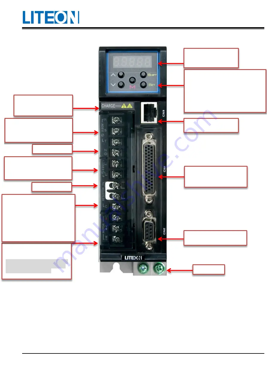
Name of each part in the servo drive
Seven-segment display: It
has five digits and shows the
drive status or alarm.
Operating button: It can be used to switch the
parameter/function and execute the
monitoring setting.
MODE: It is used to return to the previous
level or switch the status.
UP
/
DOWN: It is used to add or minus one.
SET: It is used to confirm the setting.
SHIFT: It is used to move the digit to the left.
CN3: It is used to connect to
the PC software.
CN1: It is used to connect to the
upper controller, such as the PLC
or industrial computer.
CN2: It is used to connect to the
motor encoder.
Earth terminal
Motor power output: It is used to
connect to the motor UVW cable.
Do not connect to the power supply of
the main circuit. Wrong connections
may result in drive damage!
Regenerative resistor:
1) When the external regenerative
resistor is used, the P and C ends
connect to the resistor and the P and D
ends are open-circuit.
2) When the internal regenerative
resistor is used, the P and C ends are
open-circuit and the P and D ends must
be short-circuit.
P + : DCV
BUS+
Power supply of the control circuit:
The L1 and L2 supply for the single-
phase 100~230Vac and 50/60 Hz
power supply
N - : DCV
BUS
-
Power supply of the main circuit: R,
S and T are connect to the
commercial power supply (AC
200~230 V 50/60 Hz).
Power indicator: There is
voltage remained in the main
circuit when the light is on.


