186
F(L)CS Data Acquisition
Repeat the correction ring adjustment whenever you insert a new FCS specimen.
18.1.5
Setting the Reference Position
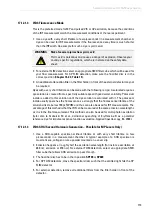
When FCS measurements are taken in solutions, the measuring point must always be
defined with the aid of a reference point. The reflection that is generated at the transition
between cover slip and specimen serves as reference.
1. To do this, proceed as described in
. Make sure that you obtain two
reflections. On the inverted microscope, the upper reflection appears at the transition
between the immersion and the cover slip; the lower reflection appears at the transition
between the cover slip and specimen (
2. On the inverted microscope, place the reflection from the cover slip/specimen-transition
approximately in the middle of the image.
3. Set the z-position to 0 on the stand.
Observe the user manuals for external lasers
Please refer to the information from the documents provided by the laser
manufacturer for the external lasers. Pay particular attention to the laser
manufacturer's notes!
4. Move the focus on the stand about 10-20
μ
m towards the specimen (positive numbers on
the inverted stand). The reflection on the inverted stand should move towards the top
edge of the image (
Figure 164:
Selection of the FCS measurement position for measurements in solutions: The reflection
between the cover slip and the solution must be above the middle of the image.
18.1.6
Acquiring a Reference Image
For measurements in cells or other structures, you will need an image of your specimen. You
can acquire this image in any step of the FCS Wizard. However, you can change the settings
for image acquisition only in the
Setup Imaging
step.
Содержание TCS SP8 SMD
Страница 1: ...10 Living up to Life User Manual Leica TCS SP8 SMD for FCS FLIM and FLCS ...
Страница 4: ...4 Copyright ...
Страница 14: ...14 Contents ...
Страница 18: ...18 Intended Use ...
Страница 20: ...20 Liability and Warranty ...
Страница 28: ...28 General Safety Notes ...
Страница 32: ...32 Additional Notes on Handling the System ...
Страница 44: ...44 System Overview and Properties ...
Страница 60: ...60 SMD Components Figure 31 DSN 102 Dual SPAD Power Supply ...
Страница 80: ...80 Safety Features ...
Страница 102: ...102 Switching On the System ...
Страница 116: ...116 LAS AF ...
Страница 214: ...214 Changing the Specimen ...
Страница 216: ...216 Changing the Objective ...
Страница 218: ...218 Piezo Focus on an Upright Microscope Figure 186 Piezo focus controller Figure 187 Spacer on objective ...
Страница 238: ...238 Switching Off the System ...
Страница 242: ...242 Repairs and Service Work ...
Страница 244: ...244 Maintenance ...
Страница 246: ...246 Disassembly and Transport ...
Страница 248: ...248 Disposal ...
Страница 254: ...254 Contact ...
Страница 256: ...256 Recommended Literature ...
Страница 266: ...266 Appendix Figure 225 Declaration of conformity ...
Страница 268: ...268 Appendix ...
Страница 269: ......


