123
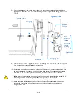
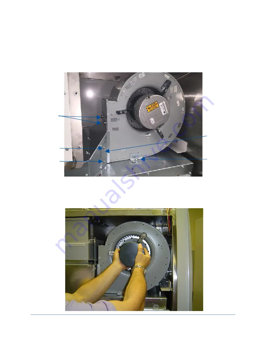
8. Using a Phillips screwdriver, remove the two sealing plate screws and remove
the sealing plate. See Figure 12-34.
9. Using a 1/2-inch socket or wrench, remove the two upper and one lower
mounting bolts. See Figure 12-34.
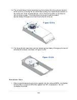
10. Grasp the motor and pull the assembly straight out of the biosafety cabinet. See
Figure 12-35.
Figure 12-34
Lower
Mounting
Bolt
Upper
Mounting
Bolts
Figure 12-35
Sealing
Plate
Sealing
Plate
Screws
Содержание Logic+ A2
Страница 148: ...148 Wiring Diagrams The wiring diagram is also located on the blower plenum cover behind the dress panel 100 115V...
Страница 149: ...149 208 240V...
Страница 151: ...151 Blower only will not start...
Страница 152: ...152 Lights only will not illuminate...
Страница 153: ...153 UV Light will not illuminate...
Страница 154: ...154 Airflow Alert activating...
Страница 155: ...155 Filter Life Gauge not at 100 when new...
Страница 156: ...156 Contamination in the work area...
Страница 200: ...200 Figure 23 4 1 2 4 3 5 7 6 8 8...
Страница 201: ...201 END OF 3849920 Figure 23 5 9 10 11 12 13...


