172
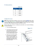
4. On the new airflow sensor, remove the two screws holding the sensor into its
body. See Figure 18-2. Do
NOT
pull the sensor out of the body.
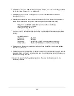
5. Position the sensor on the underneath side of the exhaust cover so that the
screen end of the sensor body is oriented towards the front of the biosafety
cabinet. Reinstall the two screws removed in the previous step through the
exhaust cover and into the sensor body. Tighten the two screws. See Figure 18-
3 for reference.
Figure 18-2
Phillips screws
Sensor
Body
Figure 18-3
Sensor
Exhaust Cover
Front of biosafety
cabinet
Содержание Logic+ A2
Страница 148: ...148 Wiring Diagrams The wiring diagram is also located on the blower plenum cover behind the dress panel 100 115V...
Страница 149: ...149 208 240V...
Страница 151: ...151 Blower only will not start...
Страница 152: ...152 Lights only will not illuminate...
Страница 153: ...153 UV Light will not illuminate...
Страница 154: ...154 Airflow Alert activating...
Страница 155: ...155 Filter Life Gauge not at 100 when new...
Страница 156: ...156 Contamination in the work area...
Страница 200: ...200 Figure 23 4 1 2 4 3 5 7 6 8 8...
Страница 201: ...201 END OF 3849920 Figure 23 5 9 10 11 12 13...


