141
Electronic Module Components
The electronics module contains the circuit breakers, AC relays, power supply board,
transition I/O board, EN Alarm/Dry Relay Contact (optional), and UV lamp ballast
(optional). These components are identified in Figure 13-1.
Figure 13-1
Outlet Circuit
Breaker(s)
Cabinet Circuit
Breaker(s)
Outlets Relay
I/O Board
LED Lamps
Relay
UV Light
Relay
Optional Gas
Valve Relay
Power Supply
Board
Optional EN
Alarm/Dry Contact
Board
UV Lamp
Ballast
Содержание Logic+ A2
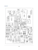
Страница 148: ...148 Wiring Diagrams The wiring diagram is also located on the blower plenum cover behind the dress panel 100 115V...
Страница 149: ...149 208 240V...
Страница 151: ...151 Blower only will not start...
Страница 152: ...152 Lights only will not illuminate...
Страница 153: ...153 UV Light will not illuminate...
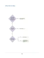
Страница 154: ...154 Airflow Alert activating...
Страница 155: ...155 Filter Life Gauge not at 100 when new...
Страница 156: ...156 Contamination in the work area...
Страница 200: ...200 Figure 23 4 1 2 4 3 5 7 6 8 8...
Страница 201: ...201 END OF 3849920 Figure 23 5 9 10 11 12 13...


