63
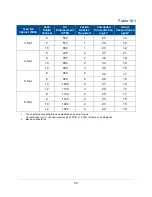
5. Open the correct number of Laskin Nozzles on the aerosol generator (refer to
Table 10-2).
6. Scan the downstream side of the supply HEPA filter by passing the sampling
nozzle in slightly overlapping strokes over the entire surface of the filter. The
sampling nozzle must be no more than 1 inch from the surface of the filter media.
Scan at a traverse rate of not more than 2 inches per second.
7. Scan the entire periphery of the supply HEPA filter, including the gasket between
the filter frame and the biosafety cabinet structure.
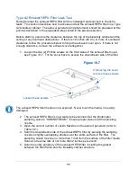
Note:
When scanning the front edge of the supply HEPA filter, photometer operation
may become erratic due to the aspiration of room air into the front of the work area.
This problem can be minimized or eliminated by placing the edge of a sheet of rigid
plastic or metal just outside the edge of the HEPA filter when scanning the front edge.
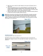
See Figure 10-13 as reference.
Acceptance Criteria
Aerosol penetration shall not exceed 0.01%.
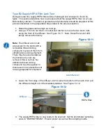
Reinstall the inlet pre-filter and diffuser, ensuring the two holes in the back of the
diffuser frame engage the posts on the rear wall of the cabinet. See Figure 10-14 for
reference.
Figure 10-13
Figure 10-14
Diffuser Pins
engaged
correctly
Содержание Logic+ A2
Страница 148: ...148 Wiring Diagrams The wiring diagram is also located on the blower plenum cover behind the dress panel 100 115V...
Страница 149: ...149 208 240V...
Страница 151: ...151 Blower only will not start...
Страница 152: ...152 Lights only will not illuminate...
Страница 153: ...153 UV Light will not illuminate...
Страница 154: ...154 Airflow Alert activating...
Страница 155: ...155 Filter Life Gauge not at 100 when new...
Страница 156: ...156 Contamination in the work area...
Страница 200: ...200 Figure 23 4 1 2 4 3 5 7 6 8 8...
Страница 201: ...201 END OF 3849920 Figure 23 5 9 10 11 12 13...


