52
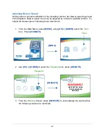
1. After selecting
Yes
on the screen to the left below and pressing
[OK/MUTE]
,
watch the Inlet Relief Valve and slowly reduce the remote exhaust system flow
until the Inlet Relief Valve begins to flutter, but is not completely closed. Hold the
remote exhaust system flow at this point. The state of the Inlet Relief Valve can
be seen on the display screen. The Inlet Relief Valve should still be
Open
. In
this state, press
[OK/MUTE]
.
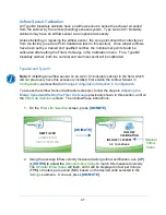
2.
When the screen below is shown, the biosafety cabinet’s internal blowers will
shut off. Using a small, flat blade screwdriver, if the VSS status shown is
Open
,
adjust the VSS set screw slowly clockwise until the VSS status changes to
Closed
. See Figure 9-4 for reference. Then slowly turn the set screw
counterclockwise until the status changes to
Open
. Because the screen is not
readily visible when adjusting the set screw, the biosafety cabinet will play an
audible alarm tone whenever the VSS status is
Closed
. Stop turning the set
screw counterclockwise when this tone stops. The VSS Calibration is complete.
3. Restore the remote exhaust system to nominal airflow. Press
[OK/MUTE]
.
YES NO
CALIBRATE VACUUM
START SWITCH?
INLET VALVE: OPEN
REDUCE EXHAUST UNTIL
INLET VALVE ALMOST CLOSED
‘OK’ TO CONTINUE
[OK/MUTE]
SWITCH: OPEN
ADJUST VSS SCREW SLOWLY
UNTIL SWITCH OPENS
‘OK’ TO CONTINUE
Figure 9-4
SET SCREW
INLET RELIEF
VALVE
VSS
Содержание Logic+ A2
Страница 148: ...148 Wiring Diagrams The wiring diagram is also located on the blower plenum cover behind the dress panel 100 115V...
Страница 149: ...149 208 240V...
Страница 151: ...151 Blower only will not start...
Страница 152: ...152 Lights only will not illuminate...
Страница 153: ...153 UV Light will not illuminate...
Страница 154: ...154 Airflow Alert activating...
Страница 155: ...155 Filter Life Gauge not at 100 when new...
Страница 156: ...156 Contamination in the work area...
Страница 200: ...200 Figure 23 4 1 2 4 3 5 7 6 8 8...
Страница 201: ...201 END OF 3849920 Figure 23 5 9 10 11 12 13...


