190
22: EN Alarm/Relay Contact Kit
All biosafety cabinets are prepared with the necessary wiring/mating components to accept a
EN Alarm/Relay Contact Kit (Catalog Number 3858320). This kit provides two funtions:
1. An audible alarm upon power loss per EN12469:2000 for microbiological safety cabinets
(primarily required in Europe).
2. A set of 3 relay contacts, which close upon three cabinet conditions:
a. Blower start is desired, and blower running
b. Blower enters reduced setback speed (NightSmart with sash closed)
c. Any alarm condition
To install the kit, follow these instructions.
Installation
A qualified electrician or certifier should install this kit.
1. Disconnect all electrical power to the biosafety cabinet by unplugging the power
cord.
2. Using a 7/16-inch socket or nut driver, remove the three acorn nuts that secure
the electronics module to the top, right side of the biosafety cabinet.
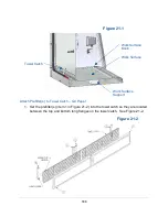
3. Tilt the electronics module on its side, and secure the module. See Figure 22-1.
4. Carefully remove the rectangular knock-out shown in Figure 22-2. It is on the left
side of the electronics module when normally positioned atop the biosafety
cabinet. The knock-
out is just above the label “Alarm Contacts”.
Figure 22-1
EN Alarm/Relay
Contact Board
(shown installed)
Содержание Logic+ A2
Страница 148: ...148 Wiring Diagrams The wiring diagram is also located on the blower plenum cover behind the dress panel 100 115V...
Страница 149: ...149 208 240V...
Страница 151: ...151 Blower only will not start...
Страница 152: ...152 Lights only will not illuminate...
Страница 153: ...153 UV Light will not illuminate...
Страница 154: ...154 Airflow Alert activating...
Страница 155: ...155 Filter Life Gauge not at 100 when new...
Страница 156: ...156 Contamination in the work area...
Страница 200: ...200 Figure 23 4 1 2 4 3 5 7 6 8 8...
Страница 201: ...201 END OF 3849920 Figure 23 5 9 10 11 12 13...


