6 | Function description
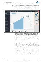
The [Management] tabulator with three dialog windows
6.12.3.1 The button [Start Adjustment]
Always perform function [Start device setup] m Calibration of the heating head po-
sitions:
– after the recommissioning of the Rework System
– after relocating the unit.
Process [Start device setup] runs guided by a wizard, similar to the wizard assisting
you through the soldering process.
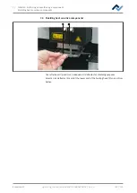
A solder nozzle must be always screwed to the pipette. For this purpose, please
also read Chapter Adjust the pipette size to the component.
CAUTION
Risk of burns from hot surfaces!
a) Touching the device surfaces may cause burns!
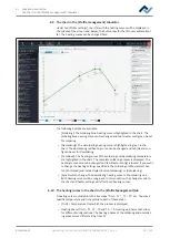
After clicking dialog [Device options] the button [Start device setup], the teaching
wizard is started. The information line above the diagram describes the working
steps to be performed.
The pipette performs a reference run.
Style
Rework
Archive
User administration
Profile management
Administration
HRSoft 2 options
Graph options
Device options
Zero Point Teach In
Back
Next
Tray Table Teach In
Vision Box Teach In
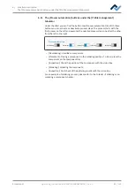
a) Click button [Next] or press the button “Next” at the bottom heating to pro-
ceed to the next work step.
b) Place both the Visionbox and the heating head in central position.
c) Place the black component tray on the right side of the bottom heating below
the pipette. Then hold down the button on the front side of the bottom heat-
ing and move the bottom heating until the component tray lies below the posi-
tion of the pipettes on the heating head.
d) Click button [Next] or press the “Next” button.
Ersa GmbH
Operating_instructions HR 500 DE 3BA00246-01 | Rev. 1
90 / 124
Содержание HR 500
Страница 2: ......
Страница 6: ......
Страница 20: ...2 Technical data PC system requirements Ersa GmbH Operating_instructions HR 500 DE 3BA00246 01 Rev 1 20 124 ...


