5 | Commissioning
Calibrate the pipette distances and the optical axle
Alignment
Desoldering
Alignment
Release
Inspection
Provide
Inspection
Soldering
Complete
Parameters
Red light intensity
Next
Back
Smaller
Split optics
White light intensity
Bigger
Component size
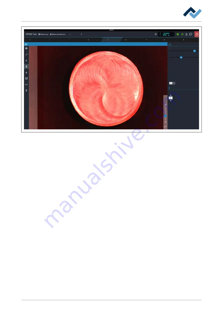
Fig. 11:
The calibration target is correctly aligned, if its margins are uniformly displayed.
g) Through control [White light intensity] set the highest possible colour contrast
of the calibration target.
h) If the calibration target is not displayed congruently on the background and no
uniform border is shown, modify the height of a machine foot. To modify it,
loosen the upper narrow lock nut at one machine foot with a 13 mm open-
ended wrench. By using the wrench screw the lower nut of the foot upwards or
downwards. Observe the camera image and correct it until the calibration tar-
get is displayed congruently on the background showing a uniform border.
i) Tighten the lock nut again.
j) If the displayed image is satisfactory, follow the final work steps described be-
low from step q).
k) If a uniform border of the calibration target cannot be reached with this
method, stop this procedure when the required image is attained as closely as
possible. Perform the following correction. You will need an Allen wrench set:
l) With a 2.5 mm Allen wrench slightly loosen the screw in the centre behind the
Visionbox (approx. ¼ rotation), see the picture below.
ð
Now the optical axles can be modified.
Ersa GmbH
Operating_instructions HR 500 DE 3BA00246-01 | Rev. 1
47 / 124
Содержание HR 500
Страница 2: ......
Страница 6: ......
Страница 20: ...2 Technical data PC system requirements Ersa GmbH Operating_instructions HR 500 DE 3BA00246 01 Rev 1 20 124 ...


