4 | Transport, installation, storage, disposal
Unpacking, setting up and connecting the Rework System
1
3
4
2
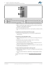
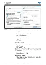
Fig. 3:
HR 500 Connections
1 Connection of the optional solder fume extractor
controller
3 Ethernet connection for optional RPC camera
2 Connection for optional RPC camera lighting
4 Ethernet connection for the PC network cable
b) Make sure that the main switch on the front of the machine is in OFF position.
c) Make sure that the local power supply and the mains frequency match the spe-
cifications on the type plate of the machine.
d) Insert the mains plug into the socket.
e) To connect the Rework Systems to the PC, insert the Ethernet cable (4) into the
PC.
As regards the pre-assembled AccuTC thermocouple:
a) Connect the thermocouple to the TC1 or TC2 socket on the right below the
component tray.
As regards the pre-assembled RPC camera:
a) Plug the lighting cable of the camera in port (2). Secure the plug with the coup-
ling nut.
b) Unscrew the screws of the cable cover plate using a 2.5 mm Allen key.
ð
The hub with its connections are now visible.
a) Connect the Ethernet cable for camera connection to the Rework System into
the port 4 of the hub. The PC is connected to port 5.
b) Lead out the cables from the hub through the openings of the cable cover plate
and screw the cover plate back on.
In case of solder fume exhaust system „Ersa Easy Arm“:
a) Plug the modular cable (RJ-12, 2 m, order no. 317096) into the socket (1) of the
soldering station.
ð
The fume extractor switches on automatically at working temperatures above
120° C.
For this purpose, please also read Chapter Assembling an RPC camera (Optional)
[
Ersa GmbH
Operating_instructions HR 500 DE 3BA00246-01 | Rev. 1
31 / 124
Содержание HR 500
Страница 2: ......
Страница 6: ......
Страница 20: ...2 Technical data PC system requirements Ersa GmbH Operating_instructions HR 500 DE 3BA00246 01 Rev 1 20 124 ...


