7 | Tutorial – Soldering or unsoldering a component
Task 2 “Desoldering”
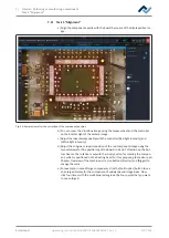
RPC Camera Live Image
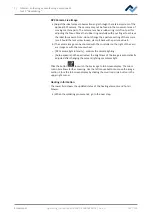
a) Adjust the ideal process observation angle through the retainer system of the
optional RPC camera. The camera may not be found in the movement area of
moving machine parts. The camera lens has a rubber ring in its front part for
adjusting the focus. Move the rubber ring carefully with your finger to achieve
the ideal focus point. Note: do not change the aperture setting of the camera
lens. Should the lens screw loosen, clamp it back with aperture value 8.
b) The camera image can be zoomed with the controller on the right of the cam-
era image or with the mouse wheel.
– [RPC camera light intensity ]: controls the camera lighting.
– [Auto exposure]: When activated, the brightness of the image is automatically
adjusted after changing the camera lighting or ambient light.
Click the button
to switch the live image to full-screen display. The zoom
controller allows further zooming. Use the left mouse button to move the image
section. Close the full-screen display by clicking the small red circle button in the
upper right corner.
Heating information
The lower field shows the updated status of the heating elements and hot air
blower.
a) When the soldering process ends, go to the next step.
Ersa GmbH
Operating_instructions HR 500 DE 3BA00246-01 | Rev. 1
107 / 124
Содержание HR 500
Страница 2: ......
Страница 6: ......
Страница 20: ...2 Technical data PC system requirements Ersa GmbH Operating_instructions HR 500 DE 3BA00246 01 Rev 1 20 124 ...


