6 | Function description
Editing the soldering profile in the [Profile management] tab and changing it permanently
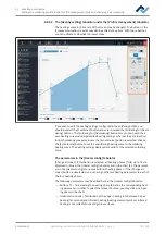
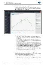
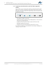
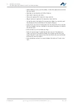
The parameters in tab [Information]
The following parameters can be changed in tab [Information]:
In field [
Profile settings
]:
– [Name]: It is defined by the profile template selection. Assign a different name
if desired. For this purpose, please also read Chapter Create, copy, delete and
save soldering profiles in the [Profile management] tabulator [
The profile templates are always referred to as “basic.”
“LF“ stands for lead free.
“SnPB“ stands for tin lead.
“Linear” stands for a uniform heating phase.
“Bent once“ stands for a heating curve with a single bend.
“Bent twice“ stands for a heating curve with two bends.
”Soak zone“ stands for heat-reduced heating phase from T1 to T2 to activate
the flux.
– [Board]: It is defined by the profile template selection (
). The templates are
called “Low and medium mass” for low to medium PCB mass, “Medium mass”
for medium PCB mass, “High mass” for high PCB mass, and “Universal,” suit-
able for each PCB type. Assign a different PCB name if desired.
– [Component]: It is defined by the profile template selection (
). The tem-
plates are called “Low and medium mass” for low to medium component mass,
“Medium mass” for medium to high component mass, “Sensitive and high
mass” for sensitive and high mass components. Assign a different component
name if desired.
– [Control sensor]: Select the temperature sensor for controlling the soldering
process via its measured temperature. [TC1] (thermocouple 1) or [TC2]. The
currently measured temperature of the selected sensor is displayed in field (2).
– [Adaptor (head)]: used adapter (air baffle). No function, only used to store in-
formation.
– [Heating head position]: Solder distance from PCB 50 mm.
– [Nozzle]: Used pipette. No function, only used to store information.
In field [
Placement
]:
– [Dip mode]: Two positioning methods are available for selection:
– [No automation]: For ordinary positioning and for the positioning of com-
ponents, which are coated with soldering paste. The component is picked
up from the component tray, aligned and placed in the soldering position.
– [Auto. Dip]: To position the components that are previously immersed in
the dip-template with flux.
– [Placement mode]: during [Placement]: Positioning of the component using the
contact sensor, or [Drop]: Dropping the component via the PCB.
– [Drop height]: during soldering: Height above the PCB at which the component
is dropped onto the PCB. Can only be changed when parameter [Drop] is selec-
ted.
For the temporary modification of the soldering profile parameters, please read
Chapter The [Information] tabulator under the [Rework] tabulator.
Ersa GmbH
Operating_instructions HR 500 DE 3BA00246-01 | Rev. 1
77 / 124
Содержание HR 500
Страница 2: ......
Страница 6: ......
Страница 20: ...2 Technical data PC system requirements Ersa GmbH Operating_instructions HR 500 DE 3BA00246 01 Rev 1 20 124 ...


