7 | Tutorial – Soldering or unsoldering a component
Task 7 “Soldering”
RPC camera live
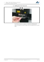
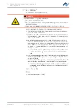
a) On the support system of the RPC camera, set the ideal angle for monitoring
the process. The camera must not be located within the operating range of the
component trays. On the front of the camera objective, you will find a rubber
ring to set the focus. Move the rubber ring carefully with a finger to focus the
camera as accurately as possible. Note: do not change the setting of the object-
ive aperture. If the locating screw of the aperture has opened, close it with
aperture value of 8.
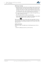
b) With the right controller, you may adjust the camera zoom.
– [RPC camera light intensity ]: Camera illumination controller.
– [Auto exposure]: If activated, the brightness of the image is automatically ad-
justed as the camera illumination is changed.
Click on the button
to view the live image in full-screen mode. You may
zoom in even more using the zoom controller. With the left mouse button you can
relocate the image detail. Close the full-screen view by clicking on the red button in
the right upper corner.
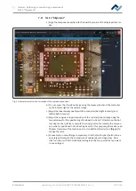
Heating information
In the lower area, the current status of the thermocouples and blower elements is
displayed.
a) When the soldering process is over, move on to the next task.
Ersa GmbH
Operating_instructions HR 500 DE 3BA00246-01 | Rev. 1
114 / 124
Содержание HR 500
Страница 2: ......
Страница 6: ......
Страница 20: ...2 Technical data PC system requirements Ersa GmbH Operating_instructions HR 500 DE 3BA00246 01 Rev 1 20 124 ...


