7 | Tutorial – Soldering or unsoldering a component
Task 5 “Alignment”
7.11 Task 5 “Alignment”
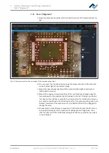
a) Align the component exactly with the board by means of the displayed live im-
age.
Alignment
Desoldering
Alignment
Release
Inspection
Provide
Inspection
Soldering
Complete
Parameters
Red light intensity
Next
Back
Smaller
Split optics
White light intensity
Bigger
Component size
Fig. 25:
Sample view after the correction of the component position
b) You can zoom the Visionbox image using the mouse wheel and the controller
on the bottom right of the camera image.
c) Adjust the ideal display quality with the controller [Red light intensity] and
[White light intensity].
d) Adjust the congruent superimposition of the red component image using the
two setscrews for fine positioning of the board in X and Y direction on the bot-
tom heater. The rotation is set with the rotary button for rotating the compon-
ent, which is positioned on the heating head. For this purpose, please also read
Chapter Overview of the machine parts. Use buttons [Smaller] and [Bigger] to
change the scale.
e) For example, in case of large components, click the [Split optics] button to see
an enlarged display for the comparison of widely spaced image areas. Now
click four times with the small blue rectangle on the four points that you want
to see enlarged.
Ersa GmbH
Operating_instructions HR 500 DE 3BA00246-01 | Rev. 1
110 / 124
Содержание HR 500
Страница 2: ......
Страница 6: ......
Страница 20: ...2 Technical data PC system requirements Ersa GmbH Operating_instructions HR 500 DE 3BA00246 01 Rev 1 20 124 ...


