5 | Commissioning
Calibrate the pipette distances and the optical axle
d) Click button [Next] or press the button “Next” at the bottom heating to pro-
ceed to the next work step.
e) Place both the heating head and the Visionbox in central position.
f) Place the black component tray on the right side of the bottom heating below
the pipette. Then hold down the button on the front side of the bottom heat-
ing and move the bottom heating by the side handles until the flat surface of
the component tray lies below the position of the pipettes on the heating
head.
g) Click button [Next] or press the “Next” button.
ð
The pipette touches the component tray.
a) Move the Visionbox to the left position, until the Visionbox is below the
pipette.
b) Click button [Next] or press the “Next” button.
ð
The pipette touches the Visionbox.
ð
After teaching-in and calibration the result is saved.
a) Click the X button to end the dialog.
Calibration Step 2: Calibrate the optical axle with the calibration target.
a) Remove the calibration target from the accessories. An open-ended wrench
size 13 will be additionally required.
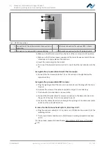
b) Place the calibration target (1) with the slightly rounded side down in the re-
cess of the component tray. The calibration target must precisely lie in hori-
zontal position in the centre of the recess.
1
c) In field [Process automation] deactivate the first work step [Desoldering], the
second work step [Placement] must be activated.
d) Click button [Start/Reference].
ð
The wizard starts at work step 4 [Provide].
Ersa GmbH
Operating_instructions HR 500 DE 3BA00246-01 | Rev. 1
45 / 124
Содержание HR 500
Страница 2: ......
Страница 6: ......
Страница 20: ...2 Technical data PC system requirements Ersa GmbH Operating_instructions HR 500 DE 3BA00246 01 Rev 1 20 124 ...


