


9.5.5. IP Wall Reader and network relay module
The IP Wall Reader consists of the following components:
1. IP Wall Reader
2. Surface-mounted housing (optional)
3. Network relay module
9.5.5.1. Terminal assignment / DIP switch at IP wall reader
On the back of the reader there is a terminal block for the wiring and a dip switch for setting the device address
of the reader.
On the terminal block 4 PINs are required, 2 for data communication and 2 for powering. The connection is
done using the pinning in the table one the right.
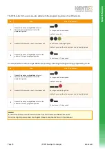
On the dip switch block the first two switches are required for the addressing.
The first IP Wall Reader connected to a network relay module always has the device address 1.
So here dip switch no. 1 has to be set to ON.
Using a second reader the reader requires address 2. Dip switch no. 2 has to be set to ON here.
Dip switch no. 5 sets the baud rate / communication speed. The default position is ON.
Page
(07-2018, subject to change)
kentix.com
69
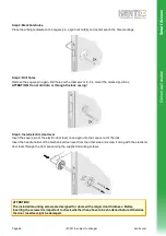
IMPORTANT!
The wiring must be done in unpowered state. The operating voltage must only be switched on after the reader
has been completely installed.
Terminal block
PIN
No.
Function
1
RS485 Data „A“
2
RS485 Data „B“
3
-
4
-
5
-
6
-
7
GND
8
8-30 V/DC
Terminal block
Dip switch block
Dip switch block
DIP
switch
Function
1
Address 1
2
Address 2
3
-
4
-
5
Baud rate
6
-
IP
w
a
ll
re
a
d
e
r
Sm
a
rt
A
c
c
e
s
s