


KE-2050/KE-2060, KE-2050R/2055R/KE-2060R Maintenance Manual
2-22
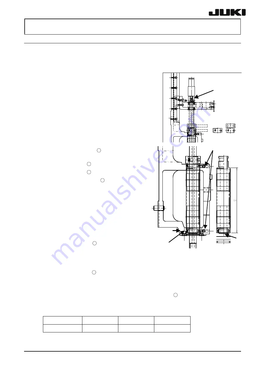
2-7. Replacing the Spline Housing
To replace the spline housing, it is necessary to detach the MNLA head and the
θ
-motor. It is also
necessary to re-input the MS parameters related to the
θ
-axis home position, Z-axis home position
adjustment, Z-axis height, and laser. (For details of input items, see section 2-9.)
(1) Detach the MNLA head following the section 2-1-1.
⑫
⑥
(2) Detach the motor cover by conducting the step (2) of
section 2-2-1.
(3) Loosen the timing belt
θ
by conducting the step (3) of
section 2-2-2.
(4) Loosen the screw fastening the MNLA bracket and
remove it from the head plate.
(5) Loosen the set collar mounting screws
h
(2 pcs.) to
remove the spline shaft from the set collar.
(6) Remove the spline shaft from the bearing of the Z-slide
bracket.
Rev. 2.00
(7) Remove the
θ
pulley
12
from the spline
housing.
(8) Loosen
the
setscrew
13
retaining the bearing.
(9) Loosen
the
setscrew
16
retaining the bearing.
(10) Remove the bearing plate
14
and pull out the
spline housing downward.
(11) Reassemble the components in the reverse
order of disassembly.
(12) While replacing, check that the thrust rubber
protrudes 50
μ
m from the head bracket with the
bearing plate removed.
(When the spline housing and the bearing have
been replaced, measure the dimensions B of
the old and new units. Increase or decrease the
thickness of the shim
15
by the dimensional
difference and the result is 50
μ
m.)
When removing the housing, the
bearing pusher rubber may be removed together with it. If this occurs, remove the
bearing setscrew
16
once, and then insert the pusher rubber.
For KE2055 and machines with the optional MNVC, when removing the bearing plate,
it is necessary to peel off the flock paper. After the housing has been replaced,
replace the flock paper with new one (40016726).
Before fix the bearing plate, push in the setscrew
16
retaining the bearing one
rotation after it hit the pusher rubber.
Tighten the bearing plate mounting screw with a tightening torque of 0.71 Nm.
Shim A (0.2 mm)
Shim B (0.1 mm)
Shim C (0.05 mm)
Shim D (0.025 mm)
40001202 40001203 40001204 40001205
Figure 2-7-1
⑬
⑭
⑮
⑯


