


KE-2050/KE-2060, KE-2050R/2055R/KE-2060R Maintenance
Manual
12-2
d
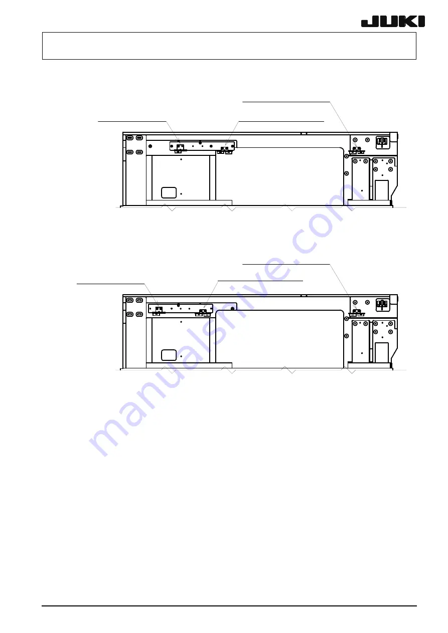
Right side
M-size
machine
FSD bracket assembly
(Rear right portion)
FSD bracket assembly
(Front right portion)
FS bracket assembly (Right)
L-size
machine
FSD bracket assembly
(Front right portion)
FSD bracket assembly
(Rear right portion)
FS bracket assembly (Right)
Figure 12-2
Rev. 2.00


