PROGRAMMING ENVIRONMENT
3-21
3
3.7.3
Process Controls (PC) Register
The PC register (
Figure 3-4
) is used to control processor activity and show the processor’s current
state. The PC register execution mode flag (bit 1) indicates that the processor is operating in either
user mode (0) or supervisor mode (1). The processor automatically sets this flag on a system call
when a switch from user mode to supervisor mode occurs and it clears the flag on a return from
supervisor mode. (User and supervisor modes are described in
section 3.8, “USER-SUPERVISOR
PROTECTION MODEL” (pg. 3-23)
.
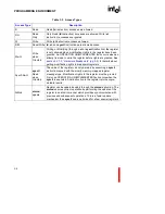
Figure 3-4. Process Controls (PC) Register
PC register state flag (bit 13) indicates the processor state: executing (0) or interrupted (1). When the
processor is servicing an interrupt, its state is interrupted. Otherwise, the processor’s state is executing.
While in the interrupted state, the processor can receive and handle additional interrupts. When
nested interrupts occur, the processor remains in the interrupted state until all interrupts are
handled, then switches back to the executing state on the return from the initial interrupt procedure.
The PC register priority field (bits 16 through 20) indicates the processor’s current executing or
interrupted priority. The architecture defines a mechanism for prioritizing execution of code,
servicing interrupts and servicing other implementation-dependent tasks or events. This
mechanism defines 32 priority levels, ranging from 0 (the lowest priority level) to 31 (the highest).
The priority field always reflects the current priority of the processor. Software can change this
priority by use of the
modpc
instruction.
28
24
20
16
12
8
4
0
31
Trace-Enable Bit - PC.te
(0) Globally disable trace faults
(1) Globally enable trace faults
Execution-Mode Flag - PC.em
(0) user mode
(1) supervisor mode
Trace-Fault-Pending - PC.tfp
(0) no fault pending
(1) fault pending
State Flag - PC.s
(0) executing
(1) interrupted
Priority Field - PC.p
(0-31) process priority
Reserved
t
e
t
s
p p
p
p
p
4
3
2
1 0
f
m
e
p
(Do not modify)
Содержание i960 Jx
Страница 1: ...Release Date December 1997 Order Number 272483 002 i960 Jx Microprocessor Developer s Manual ...
Страница 24: ......
Страница 25: ...1 INTRODUCTION ...
Страница 26: ......
Страница 35: ...2 DATA TYPES AND MEMORY ADDRESSING MODES ...
Страница 36: ......
Страница 46: ......
Страница 47: ...3 PROGRAMMING ENVIRONMENT ...
Страница 48: ......
Страница 73: ...4 CACHE AND ON CHIP DATA RAM ...
Страница 74: ......
Страница 85: ...5 INSTRUCTION SET OVERVIEW ...
Страница 86: ......
Страница 111: ...6 INSTRUCTION SET REFERENCE ...
Страница 112: ......
Страница 195: ...INSTRUCTION SET REFERENCE 6 83 6 Opcode mov 5CCH REG movl 5DCH REG movt 5ECH REG movq 5FCH REG See Also LOAD STORE lda ...
Страница 233: ...7 PROCEDURE CALLS ...
Страница 234: ......
Страница 256: ......
Страница 257: ...8 FAULTS ...
Страница 258: ......
Страница 291: ...9 TRACING AND DEBUGGING ...
Страница 292: ......
Страница 309: ...10 TIMERS ...
Страница 310: ......
Страница 324: ......
Страница 325: ...11 INTERRUPTS ...
Страница 326: ......
Страница 369: ...12 INITIALIZATION AND SYSTEM REQUIREMENTS ...
Страница 370: ......
Страница 412: ......
Страница 413: ...13 MEMORY CONFIGURATION ...
Страница 414: ......
Страница 429: ...14 EXTERNAL BUS ...
Страница 430: ......
Страница 468: ......
Страница 469: ...15 TEST FEATURES ...
Страница 470: ......
Страница 493: ...A CONSIDERATIONS FOR WRITING PORTABLE CODE ...
Страница 494: ......
Страница 502: ......
Страница 503: ...B OPCODES AND EXECUTION TIMES ...
Страница 504: ......
Страница 515: ...C MACHINE LEVEL INSTRUCTION FORMATS ...
Страница 516: ......
Страница 523: ...D REGISTER AND DATA STRUCTURES ...
Страница 524: ......
Страница 550: ......
Страница 551: ...GLOSSARY ...
Страница 552: ......
Страница 561: ...INDEX ...
Страница 562: ......
Страница 578: ......


