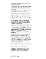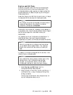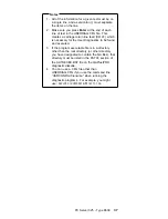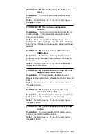
configuration information file (see “EISA Configuration
Advanced Function” on page 26).
3. Change configuration resource allocations. Use the
built-in Setup program to view or change system
board resource allocations. Use the Advanced
selection of the EISA Configuration Diskette's View or
edit details screen to view the available or the used
system resources (see “EISA Configuration Advanced
Function” on page 26). Use the Edit Changes
selection to change resource allocations for complex
configurations.
4. Change adapter jumpers or switches. Jumpers and
switches define the system resources that a device
can use. If the settings are incorrect or set to use a
resource that cannot be shared, a conflict occurs and
the device remains deactivated by the configuration
program. Use the EISA Configuration Diskette's Step
4, Examine switches or print report screen to verify
switches (see “EISA Configuration Menu Selections”
on page 24). Read the documentation supplied with
the device.
5. Change system board jumpers or switches. Remove
the cover; then, refer to the system-board diagram
inside the server.
6. Remove the device or adapter. Some configurations
are not supported (for example, you cannot operate
the server with two PCI SVGA adapters installed).
7. Assign EISA memory addresses starting with DFFFF
(in hexadecimal), and work downward to address
C8000 (in hexadecimal). PCI devices are
automatically assigned memory addresses starting
from C8000 working upwards.
Resolving Software Configuration
Conflicts:
The memory-address space and interrupt levels (IRQs)
used by some hardware options might conflict with
addresses defined for use through application programs or
through use by Expanded Memory Specification, EMS.
(EMS is used only with DOS.)
If there is a conflict, one or more of the following conditions
might exist:
The system cannot load the operating system.
The system does not work.
An application program does not operate, or it returns
an error.
Screen messages indicate a conflict exists.
You can resolve conflicts by changing either the software
or the hardware configuration.
32
PC Server HMM
Содержание 8639 - PC Server 325
Страница 97: ...Drawer Model Rails Drives 92 PC Server HMM...
Страница 102: ...Operator Panel and Cable Note Loosen do not remove screw Screw PC Server 325 Type 8639 97...
Страница 108: ...System Board Note Note A black square indicates pin 1 PC Server 325 Type 8639 103...
Страница 120: ...Parts Listings 1 2 3 4 5 6 7 8 9 10 12 11 13 14 15 16 17 18 20 19 PC Server 325 Type 8639 115...
Страница 121: ...21 23 24 25 22 26 27 28 29 30 116 PC Server HMM...
Страница 129: ...124 PC Server HMM...
Страница 145: ...IBM Part Number 84H3049 Printed in U S A S84H 3 49...


