Connections and Setup
FF-SM Series Installation Manual
46 Honeywell
•
PK 107007-01 EN FR26 GLO 0298 Printed in France
For application help: see Warranty Information
Setup
Excess Gain Adjustment After Installation
IMPROPER USE OF THE FF-SM SERIES SAFETY MAT
•
The 30 kg sensitivity of the FF-SM Series safety mats is suitable for the detection of adults weighing
more than 35 kg according to the EN1760-1 European standard.
•
Do NOT use FF-SM Series safety mats in public places where children may have to be detected.
•
Use of an additional protective sheet laid on the safety mat (sensor) surface is forbidden since it may
alter the 30 kg sensitivity.
Failure to comply with these instructions will result in death or serious injury.
IMPROPER GAIN ADJUSTMENT
•
Never perform the excess gain adjustment with an individual or object on the sensing surface of the
safety mat.
•
Do not use the safety mat until the excess gain adjustment has been performed correctly as indicated
by an illuminated green light on the control box.
Improper gain adjustment will result in keeping the product in alarm.
IMPROPER CONTROL UNIT MAINTENANCE
•
Access to the control unit is restricted to adjusting excess gain (DT1, DT2), making ST optical
connections using snap-in clips, replacing supply fuses, and connecting wires.
•
Do not touch any other components inside the control unit.
Failure to comply with these instructions could result in death or serious injury.
Perform an excess gain adjustment twenty-four hours after installation to compensate for mat
(sensor) settling and to ensure proper operation.
This excess gain adjustment must be performed after all mats and accessories are installed
and without any target (object) on the sensing zone. This adjustment corrects for any initial
signal attenuation due to conditions of use (e.g., number of safety mats connected in series to
a single control unit, type of coating, quality of floor on which safety mat is laid). The control
unit is preset to detect a minimum mass of 30 kg (66.1 lb.) after the adjustment is made.
Therefore, this adjustment is not a sensitivity adjustment. The control unit remains in an alarm
condition if the adjustment is not done correctly.
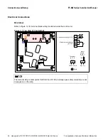
A range selector switch and multi-turn potentiometer are used to adjust excess gain. These
adjustments are located on a printed circuit board in the control unit. A status indicator can be
seen on the front panel of the control unit. Five additional light emitting diodes (LEDs) are
located on the same circuit board and provide visual information related to signal margin
(these LEDs cannot be seen by the operator when the cover is installed).
Содержание SYA14 Series
Страница 2: ...2 107031 23 EN FR26 GLO 1199 Printed in France This page has been left intentionally blank ...
Страница 6: ...6 107031 23 EN FR26 GLO 1199 Printed in France This page has been left intentionally blank ...
Страница 26: ...26 107031 23 EN FR26 GLO 1199 Printed in France This page has been left intentionally blank ...
Страница 62: ...62 107031 23 EN FR26 GLO 1199 Printed in France This page has been left intentionally blank ...
Страница 70: ...70 107031 23 EN FR26 GLO 1199 Printed in France This page has been left intentionally blank ...
Страница 76: ...76 107031 23 EN FR26 GLO 1199 Printed in France This page has been left intentionally blank ...
Страница 78: ...78 107031 23 EN FR26 GLO 1199 Printed in France This page has been left intentionally blank ...
Страница 79: ...107031 23 EN FR26 GLO 1199 Printed in France 79 8 CE Declaration of Conformity ...
Страница 80: ...80 107031 23 EN FR26 GLO 1199 Printed in France This page has been left intentionally blank ...
Страница 84: ......
Страница 158: ......
Страница 160: ......
Страница 161: ...For application help call 1 800 537 6945 Honeywell MICRO SWITCH Sensing and Control 80 ...
Страница 165: ...3 107022 14 EN FR26 GLO 0100 Printed in Germany This page has been left intentionally blank ...
Страница 201: ...39 107022 14 EN FR26 GLO 0100 Printed in Germany This page has been left intentionally blank ...
Страница 205: ...43 107022 14 EN FR26 GLO 0100 Printed in Germany This page has been left intentionally blank ...
Страница 207: ...45 107022 14 EN FR26 GLO 0100 Printed in Germany This page has been left intentionally blank ...
Страница 208: ...107022 14 EN FR26 GLO 0100 Printed in Germany 46 9 Declaration of Conformity ...
Страница 219: ...11 107006 11 EN FR26 GLO 0300 Printed in Germany This page has been left intentionally blank ...
Страница 229: ...21 107006 11 EN FR26 GLO 0300 Printed in Germany This page has been left intentionally blank ...
Страница 257: ...49 107006 11 EN FR26 GLO 0300 Printed in Germany This page has been left intentionally blank ...
Страница 260: ...107006 11 EN FR26 GLO 0300 Printed in Germany 52 9 3 Declaration of conformity ...
Страница 263: ...PK 107007 1 EN FR26 GLO 298 Printed in France Safety Mat Installation Manual FF SM Series Safety Mat PK 107007 Issue 1 ...
Страница 264: ...ii Honeywell PK 107007 01 EN FR26 GLO 0298 Printed in France For application help see Warranty Information ...
Страница 340: ...Safety Perimeter Guarding Installation Manual FF SPS4 Series Safety Perimeter Guarding ...
Страница 536: ...2 107004 15 EN FR26 ROW 0899 Printed in France This page has been left intentionally blank ...
Страница 538: ...4 107004 15 EN FR26 ROW 0899 Printed in France This page has been left intentionally blank ...
Страница 542: ...107004 15 EN FR26 ROW 0899 Printed in France 8 This page has been left intentionally blank ...
Страница 620: ...86 107004 15 EN FR26 ROW 0899 Printed in France This page has been left intentionally blank ...
Страница 624: ...90 107004 15 EN FR26 ROW 0899 Printed in France This page has been left intentionally blank ...
Страница 626: ...92 107004 15 EN FR26 ROW 0899 Printed in France This page has been left intentionally blank ...
Страница 627: ...107004 15 EN FR26 ROW 0899 Printed in France 93 8 CE Declaration of Conformity ...
Страница 628: ...94 107004 15 EN FR26 ROW 0899 Printed in France This page has been left intentionally blank ...


