35
107022-14 EN FR26 GLO 0100 Printed in Germany
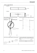
Figure 5-1 Safety Equipment Test Rod Detection
Table 5-1 Summary of Inspection and Test Methods
Inspect and Test
Method
Frequency
Object detection and
machine reaction
•
Insert a 30 mm or 14 mm diameter test rod into
the light curtain sensing field and ensure the
machine stops.
Daily, at each power up, and after each
intervention (or maintenance)
performed on the protective safety
equipment
Operation of the machine
control circuitry
•
Test function generated by the machine (closing
an external normally open contact located in the
“test loop” of the FF-LS control unit)
Each time the machine is used or as
part of each cycle
Output relay
•
Count the machines cycles and evaluate the
number of operations.
1,000,000 operations (1.5 A/220 Vac,
1.5 A / 24 Vdc) or every 3 years if
protective RC elements are mounted
Enclosure
•
Visually inspect enclosure to ensure the control
unit is closed and locked. The key should be
kept by an appointed person.
Based on environment and needs
Electrical wiring
•
Visually inspect the safety light curtain and the
electrical wiring to ensure that they are in
serviceable condition.
Based on environment and needs
Cleaning
•
Use a clean, soft, dry cloth for dust removal.
•
Use a clean, soft cloth with soapy water for
grease removal.
•
Wipe without rubbing (rubbing causes streaks
and static electricity that attracts dust).
•
Products used to clean windows may be used.
•
Never use solvents like petrol, white spirit,
trichlorœthane, trichlorœtylene, or acetone.
Based on environment and needs
5.2
Control Unit Status Indicators
POWER APPLIED TO MACHINE CONTROL SYSTEM
Before intervention, turn off and disconnect power from FF-LS Series safety light curtain and machine.
Failure to comply with these instructions could result in death or serious injury.
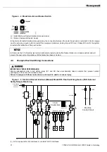
The control unit has seven status indicator LEDs (see below). The green status LEDs 1, 2 and 3 are always illuminated if
the supply voltage is present. The yellow status LEDs 4 and 6, the red status LEDs 5 and 7 and a buzzer (acoustic signal)
are used to determine the operational status of the safety equipment. This buzzer (acoustic signal) can be switched on or off
using the buzzer switch located on the control unit printed circuit board (see figure 5-2).
ø 14 mm or ø 30 mm test rod
Содержание SYA14 Series
Страница 2: ...2 107031 23 EN FR26 GLO 1199 Printed in France This page has been left intentionally blank ...
Страница 6: ...6 107031 23 EN FR26 GLO 1199 Printed in France This page has been left intentionally blank ...
Страница 26: ...26 107031 23 EN FR26 GLO 1199 Printed in France This page has been left intentionally blank ...
Страница 62: ...62 107031 23 EN FR26 GLO 1199 Printed in France This page has been left intentionally blank ...
Страница 70: ...70 107031 23 EN FR26 GLO 1199 Printed in France This page has been left intentionally blank ...
Страница 76: ...76 107031 23 EN FR26 GLO 1199 Printed in France This page has been left intentionally blank ...
Страница 78: ...78 107031 23 EN FR26 GLO 1199 Printed in France This page has been left intentionally blank ...
Страница 79: ...107031 23 EN FR26 GLO 1199 Printed in France 79 8 CE Declaration of Conformity ...
Страница 80: ...80 107031 23 EN FR26 GLO 1199 Printed in France This page has been left intentionally blank ...
Страница 84: ......
Страница 158: ......
Страница 160: ......
Страница 161: ...For application help call 1 800 537 6945 Honeywell MICRO SWITCH Sensing and Control 80 ...
Страница 165: ...3 107022 14 EN FR26 GLO 0100 Printed in Germany This page has been left intentionally blank ...
Страница 201: ...39 107022 14 EN FR26 GLO 0100 Printed in Germany This page has been left intentionally blank ...
Страница 205: ...43 107022 14 EN FR26 GLO 0100 Printed in Germany This page has been left intentionally blank ...
Страница 207: ...45 107022 14 EN FR26 GLO 0100 Printed in Germany This page has been left intentionally blank ...
Страница 208: ...107022 14 EN FR26 GLO 0100 Printed in Germany 46 9 Declaration of Conformity ...
Страница 219: ...11 107006 11 EN FR26 GLO 0300 Printed in Germany This page has been left intentionally blank ...
Страница 229: ...21 107006 11 EN FR26 GLO 0300 Printed in Germany This page has been left intentionally blank ...
Страница 257: ...49 107006 11 EN FR26 GLO 0300 Printed in Germany This page has been left intentionally blank ...
Страница 260: ...107006 11 EN FR26 GLO 0300 Printed in Germany 52 9 3 Declaration of conformity ...
Страница 263: ...PK 107007 1 EN FR26 GLO 298 Printed in France Safety Mat Installation Manual FF SM Series Safety Mat PK 107007 Issue 1 ...
Страница 264: ...ii Honeywell PK 107007 01 EN FR26 GLO 0298 Printed in France For application help see Warranty Information ...
Страница 340: ...Safety Perimeter Guarding Installation Manual FF SPS4 Series Safety Perimeter Guarding ...
Страница 536: ...2 107004 15 EN FR26 ROW 0899 Printed in France This page has been left intentionally blank ...
Страница 538: ...4 107004 15 EN FR26 ROW 0899 Printed in France This page has been left intentionally blank ...
Страница 542: ...107004 15 EN FR26 ROW 0899 Printed in France 8 This page has been left intentionally blank ...
Страница 620: ...86 107004 15 EN FR26 ROW 0899 Printed in France This page has been left intentionally blank ...
Страница 624: ...90 107004 15 EN FR26 ROW 0899 Printed in France This page has been left intentionally blank ...
Страница 626: ...92 107004 15 EN FR26 ROW 0899 Printed in France This page has been left intentionally blank ...
Страница 627: ...107004 15 EN FR26 ROW 0899 Printed in France 93 8 CE Declaration of Conformity ...
Страница 628: ...94 107004 15 EN FR26 ROW 0899 Printed in France This page has been left intentionally blank ...

