GSS Series
Issue 2
PK 80086
2
Honeywell
•
MICRO SWITCH Sensing and Control
WARNUNG
•
UNSACHGEMÄSSER EINBAU
•
Beraten Sie sich mit den zuständigen Sicherheitsbehörden
beim Entwurf von Verbindungen zu Maschinensteuerungen,
Schnittstellen und sämtlichen Steuerelementen, welche die
Sicherheit betreffen.
•
Halten Sie sich genau an die Einbau-Anweisungen.
Das Nichtbeachten dieser Anweisungen könnte zum Tod oder
zu schweren Verletzungen führen.
SCHALTER MONTIEREN, ANSCHLIESSEN UND ABDICHTEN
WARNUNG
UNSACHGEMÄSSER BETRIEB
•
Sicherstellen, daß der Betätiger genügend Laufweg hat, um die
Öffnerkontakte (NC) zwangszuöffnen.
Das Nichtbeachten dieser Anweisungen könnte zum Tod oder
zu schweren Verletzungen führen.
1. Weitere
Informationen:
•
Einstellungen auf Seite 3.
•
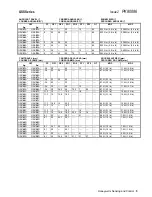
EN 50041 Schaltungskonfigurationen für jeden
Schaltercode auf Seite 4. (Ag=Silberkontakte,
Au=Goldplattierte Kontakte)
•
Spezifische Laufwege für jeden Schaltercode und
technische Daten auf Seite 5 und 6.
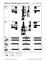
•
Ordnungsgemäße Anwendung von Positionsschaltern und
Abmessungen für die Schaltermontage auf Seite 7.
2. Einstellungen vornehmen (falls gewünscht). Den im
Lieferumfang enthaltenen, manipulationssicheren TORX
-
Einsatz verwenden:
•
Ausrichtung des Kopfes (Abbildung 1).
•
Betätigungsrichtung (Abbildung 2).
•
Schalter mit seitlichem Schwenkhebel mit 90
°
-
Zwangssteuerhebeln (Bestellnummern enden mit A1A,
A1B, A5A, A5B) (Abbildung 3):
−
Sicherstellen, daß die gegenüberliegenden Flächen des
Schalterschafts in die Rille im Betätigerhebel eingreifen.
−
Die Sicherungsschraube (A) anziehen, bis die Nase (B)
nicht mehr zu bewegen ist.
3. Den Schalter mit Hilfe von vier M5-Schrauben oder Schrauben
Nr. 10 montieren. Schrauben mit 4,9 ...1,80 Nm anziehen.
4. Die manipulationssicheren Schrauben auf der Deckplatte
entfernen.
5. Den Litzendraht (0,75 mm
2
... 2,5 mm
2
, 18 ... 14 AWG) oder
Draht (0,75 mm
2
... 1,5 mm
2
, 18 ...16 AWG) an die
Klemmleisten anschließen (90
°
C-Draht verwenden, wenn die
Umgebungstemperatur über 75
°
C liegt). Die
Klemmleistenschrauben des Schalters mit 0,8 ...1,0 Nm
anziehen.
6. Die Kabeleinführung entsprechend den Anweisungen in PK
80112 abdichten.
7. Die Deckplatte wieder montieren.
AVERTISSEMENT
INSTALLATION INCORRECTE
•
Faites appel à des organismes locaux de sécurité et prenez en
compte leurs exigences lorsque vous concevez une liaison de
commande ou interface de machine, ou tout autre dispositif de
commande mettant en jeu la sécurité.
•
Respectez scrupuleusement l’ensemble des instructions
d’installation.
L’inobservation de ces instructions peut entraîner la mort ou
de graves blessures.
MONTEZ, CABLEZ ET ETANCHEIFIEZ L'INTERRUPTEUR
AVERTISSEMENT
MAUVAIS FONCTIONNEMENT
•
Veillez à ce que l’actionneur de l’interrupteur parcourt une
course suffisante afin de permettre une ouverture positive des
contacts normalement fermés (NF).
L’inobservation de ces instructions peut entraîner la mort ou
de graves blessures.
1. Consultez
:
•
La page 3 pour les réglages.
•
La page 4 pour les configurations de câblage EN 50041
pour chaque code d’interrupteur. (Ag = contacts en argent,
Au = contacts dorés)
•
Les pages 5 et 6 pour connaître les longueurs de courses
pour chaque code d’interrupteur et les caractéristiques
techniques.
•
La page 7 pour savoir comment réaliser une application
correcte des interrupteurs de fin de course et connaître les
cotes de montage de l'interrupteur.
2. Effectuez les réglages (le cas échéant). Utilisez l’embout
inviolable TORX
(inclus) pour :
•
Orientation de la tête (figure 1).
•
Sens d’actionnement (figure 2).
•
Interrupteurs à rotation latérale avec leviers à 90
°
à action
positive (numéros de référence se terminant par A1A, A1B,
A5A, A5B) (figure 3) :
−
Veillez à ce que les méplats de l’axe de l’interrupteur
s’engagent dans l’encoche du levier de l’actionneur.
−
Serrez la vis de blocage (A) jusqu’à ce que la languette
(B) ne bouge plus.
3. Montez l’interrupteur à l’aide de vis M5 ou n°10. Serrez les vis
avec un couple de 4,9 à 5,9 N.m (43 à 52 in.lb).
4. Retirez les vis inviolables du couvercle.
5. Connectez du fil souple (0,75 mm
2
à 2,5 mm
2
, 18 à 14 AWG)
ou rigide (0,75 mm
2
à 1,5 mm
2
, 18 à 16 AWG) aux bornes du
connecteur (utilisez du fil 90
°
C lorsque la température
ambiante est supérieure à 75
°
C). Serrez les vis des bornes
de l’interrupteur avec un couple de 0,8 à 1,0 N.m (7 à 9 in.lb).
6. Réalisez l'étanchéité de l’ouverture du conduit conformément
aux instructions données en PK 80112.
7. Remontez le couvercle.
Содержание SYA14 Series
Страница 2: ...2 107031 23 EN FR26 GLO 1199 Printed in France This page has been left intentionally blank ...
Страница 6: ...6 107031 23 EN FR26 GLO 1199 Printed in France This page has been left intentionally blank ...
Страница 26: ...26 107031 23 EN FR26 GLO 1199 Printed in France This page has been left intentionally blank ...
Страница 62: ...62 107031 23 EN FR26 GLO 1199 Printed in France This page has been left intentionally blank ...
Страница 70: ...70 107031 23 EN FR26 GLO 1199 Printed in France This page has been left intentionally blank ...
Страница 76: ...76 107031 23 EN FR26 GLO 1199 Printed in France This page has been left intentionally blank ...
Страница 78: ...78 107031 23 EN FR26 GLO 1199 Printed in France This page has been left intentionally blank ...
Страница 79: ...107031 23 EN FR26 GLO 1199 Printed in France 79 8 CE Declaration of Conformity ...
Страница 80: ...80 107031 23 EN FR26 GLO 1199 Printed in France This page has been left intentionally blank ...
Страница 84: ......
Страница 158: ......
Страница 160: ......
Страница 161: ...For application help call 1 800 537 6945 Honeywell MICRO SWITCH Sensing and Control 80 ...
Страница 165: ...3 107022 14 EN FR26 GLO 0100 Printed in Germany This page has been left intentionally blank ...
Страница 201: ...39 107022 14 EN FR26 GLO 0100 Printed in Germany This page has been left intentionally blank ...
Страница 205: ...43 107022 14 EN FR26 GLO 0100 Printed in Germany This page has been left intentionally blank ...
Страница 207: ...45 107022 14 EN FR26 GLO 0100 Printed in Germany This page has been left intentionally blank ...
Страница 208: ...107022 14 EN FR26 GLO 0100 Printed in Germany 46 9 Declaration of Conformity ...
Страница 219: ...11 107006 11 EN FR26 GLO 0300 Printed in Germany This page has been left intentionally blank ...
Страница 229: ...21 107006 11 EN FR26 GLO 0300 Printed in Germany This page has been left intentionally blank ...
Страница 257: ...49 107006 11 EN FR26 GLO 0300 Printed in Germany This page has been left intentionally blank ...
Страница 260: ...107006 11 EN FR26 GLO 0300 Printed in Germany 52 9 3 Declaration of conformity ...
Страница 263: ...PK 107007 1 EN FR26 GLO 298 Printed in France Safety Mat Installation Manual FF SM Series Safety Mat PK 107007 Issue 1 ...
Страница 264: ...ii Honeywell PK 107007 01 EN FR26 GLO 0298 Printed in France For application help see Warranty Information ...
Страница 340: ...Safety Perimeter Guarding Installation Manual FF SPS4 Series Safety Perimeter Guarding ...
Страница 536: ...2 107004 15 EN FR26 ROW 0899 Printed in France This page has been left intentionally blank ...
Страница 538: ...4 107004 15 EN FR26 ROW 0899 Printed in France This page has been left intentionally blank ...
Страница 542: ...107004 15 EN FR26 ROW 0899 Printed in France 8 This page has been left intentionally blank ...
Страница 620: ...86 107004 15 EN FR26 ROW 0899 Printed in France This page has been left intentionally blank ...
Страница 624: ...90 107004 15 EN FR26 ROW 0899 Printed in France This page has been left intentionally blank ...
Страница 626: ...92 107004 15 EN FR26 ROW 0899 Printed in France This page has been left intentionally blank ...
Страница 627: ...107004 15 EN FR26 ROW 0899 Printed in France 93 8 CE Declaration of Conformity ...
Страница 628: ...94 107004 15 EN FR26 ROW 0899 Printed in France This page has been left intentionally blank ...


