Maintained Explosion-proof Cable Pull Limit Switch
PK 81593
For application help: call 1-800-537-6945
Honeywell
•
MICRO SWITCH Sensing and Control 3
Step 2 - Attach cable to switch:
•
Ensure cable is fully seated and tightly fitted in the
thimble groove.
•
Attach using two U-bolt clamps. U-bolt clamps
should be installed as close as possible to
thimble.
•
Tighten U-bolts to 4.5 in.-lb. (0,51 N-m) for 1/8 in.
(3,18 mm) cable and 7.5 in.-lb. (0,85 N-m) for
3/16 in. (4,76 mm) cable.
Step 3 - Install cable supports:
SWITCH DAMAGE
Do NOT allow excessive side loads that could
bend the switch operating shaft. Failure to comply
with these instructions may result in product
damage.
•
Install a cable support as close as practical to end
of shaft without interfering with switch operation.
•
If cable tension adjusting turnbuckle is in mid-
span of cable, the first cable support should be in
line with, and no further than, 12 in. (30 cm) from
end (eye) of shaft. If adjusting turnbuckle is
attached directly to shaft eye, this distance may
be increased to 18 in. (46 cm).
•
Support cable at intervals no greater than 8 ft.
(2,4 m).
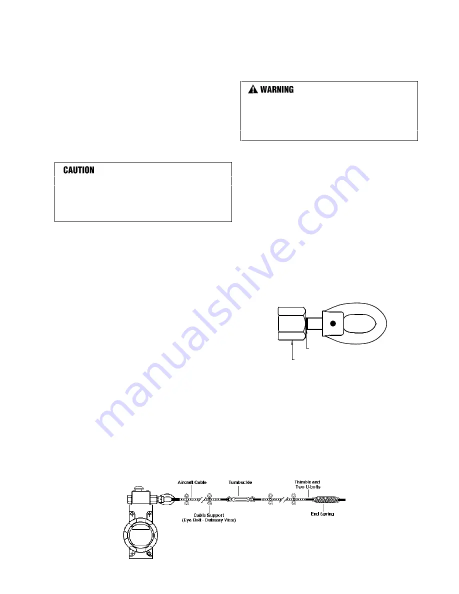
REQUIRED ENDSPRING AND TURNBUCKLE
INSTALLATION (Figure 3)
Step 1 - Ensure you have the following
•
Endspring, turnbuckle, jam nuts (supplied with
switch).
•
Thimbles, U-bolt clamps.
Step 2 - Install endspring: Reduces effects of
ambient temperature fluctuations and provides a
measure of protection against excessive force being
applied to cable.
•
Install an endspring within cable span, preferably
at end
of cable opposite switch (see Actuating
Cable Installation, Step 2).
Step 3 - Install turnbuckle: Ensures proper cable
tension.
IMPROPER INSTALLATION
Do NOT install turnbuckle too closely to cable
supports or other barriers that may hinder proper
operation. Failure to comply with these instructions
could result in death or serious injury.
•
Install within cable span in same manner as
endspring. Use jam nuts to maintain adjustment.
REQUIRED CABLE TENSION ADJUSTMENT
Step 1 - Align colored tension indicator line:
•
Tighten turnbuckle until colored tension indicator
line on switch plunger starts to appear from within
switch operating head.
Step 2 - Ensure proper adjustment (Figure 4):
•
Ensure tension indicator line is visible and aligned
with end of guide bushing on operating head.
•
Periodically check and adjust cable tension as
necessary.
Figure 4: Cable Tension at Proper Setting
Tension Indicator Line
Guide Bushing
With endspring installed, switch/cable will operate
satisfactorily over a temperature range of +/-25°F
(+/-12°C), up to maximum cable length of 200 ft.
(60 m).
Adjust cable tension when ambient temperature is
near mid point of expected temperature extremes.
Figure 3: Switch with Turnbuckle and Endspring
Содержание SYA14 Series
Страница 2: ...2 107031 23 EN FR26 GLO 1199 Printed in France This page has been left intentionally blank ...
Страница 6: ...6 107031 23 EN FR26 GLO 1199 Printed in France This page has been left intentionally blank ...
Страница 26: ...26 107031 23 EN FR26 GLO 1199 Printed in France This page has been left intentionally blank ...
Страница 62: ...62 107031 23 EN FR26 GLO 1199 Printed in France This page has been left intentionally blank ...
Страница 70: ...70 107031 23 EN FR26 GLO 1199 Printed in France This page has been left intentionally blank ...
Страница 76: ...76 107031 23 EN FR26 GLO 1199 Printed in France This page has been left intentionally blank ...
Страница 78: ...78 107031 23 EN FR26 GLO 1199 Printed in France This page has been left intentionally blank ...
Страница 79: ...107031 23 EN FR26 GLO 1199 Printed in France 79 8 CE Declaration of Conformity ...
Страница 80: ...80 107031 23 EN FR26 GLO 1199 Printed in France This page has been left intentionally blank ...
Страница 84: ......
Страница 158: ......
Страница 160: ......
Страница 161: ...For application help call 1 800 537 6945 Honeywell MICRO SWITCH Sensing and Control 80 ...
Страница 165: ...3 107022 14 EN FR26 GLO 0100 Printed in Germany This page has been left intentionally blank ...
Страница 201: ...39 107022 14 EN FR26 GLO 0100 Printed in Germany This page has been left intentionally blank ...
Страница 205: ...43 107022 14 EN FR26 GLO 0100 Printed in Germany This page has been left intentionally blank ...
Страница 207: ...45 107022 14 EN FR26 GLO 0100 Printed in Germany This page has been left intentionally blank ...
Страница 208: ...107022 14 EN FR26 GLO 0100 Printed in Germany 46 9 Declaration of Conformity ...
Страница 219: ...11 107006 11 EN FR26 GLO 0300 Printed in Germany This page has been left intentionally blank ...
Страница 229: ...21 107006 11 EN FR26 GLO 0300 Printed in Germany This page has been left intentionally blank ...
Страница 257: ...49 107006 11 EN FR26 GLO 0300 Printed in Germany This page has been left intentionally blank ...
Страница 260: ...107006 11 EN FR26 GLO 0300 Printed in Germany 52 9 3 Declaration of conformity ...
Страница 263: ...PK 107007 1 EN FR26 GLO 298 Printed in France Safety Mat Installation Manual FF SM Series Safety Mat PK 107007 Issue 1 ...
Страница 264: ...ii Honeywell PK 107007 01 EN FR26 GLO 0298 Printed in France For application help see Warranty Information ...
Страница 340: ...Safety Perimeter Guarding Installation Manual FF SPS4 Series Safety Perimeter Guarding ...
Страница 536: ...2 107004 15 EN FR26 ROW 0899 Printed in France This page has been left intentionally blank ...
Страница 538: ...4 107004 15 EN FR26 ROW 0899 Printed in France This page has been left intentionally blank ...
Страница 542: ...107004 15 EN FR26 ROW 0899 Printed in France 8 This page has been left intentionally blank ...
Страница 620: ...86 107004 15 EN FR26 ROW 0899 Printed in France This page has been left intentionally blank ...
Страница 624: ...90 107004 15 EN FR26 ROW 0899 Printed in France This page has been left intentionally blank ...
Страница 626: ...92 107004 15 EN FR26 ROW 0899 Printed in France This page has been left intentionally blank ...
Страница 627: ...107004 15 EN FR26 ROW 0899 Printed in France 93 8 CE Declaration of Conformity ...
Страница 628: ...94 107004 15 EN FR26 ROW 0899 Printed in France This page has been left intentionally blank ...


