FF-SRT Series
ISSUE 1
PK107019-01
PK107019-01-EN FR26 GLO 398 Printed in Germany
3
MECHANICAL INSTALLATION
The FF-SRT must be installed inside a NEMA 3 (IEC IP54)
rating enclosure or better. The module can be clipped
easily onto a 45mm width DIN rail (see figures 3 and 4
below for installation and removal).
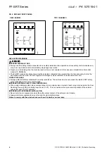
FIG 3. MOUNTING DIMENSIONS
(for reference only)
FIG 4. INSTALLATION DIAGRAM
CONTROL RELIABILITY
“Control Reliability” means that “the device, system or
interface shall be designed, constructed and installed such
that a single component failure within the device, interface
or system shall not prevent normal stopping action from
taking place but shall prevent a successive machine cycle.”
(ANSI B11.19-1990, 5.5)
OSHA 29 CFR 1910.217 states that “the control system
shall be constructed so that a failure within the system does
not prevent the normal stopping action from being applied
to the press when required, but does prevent initiation of a
successive stroke until the failure is corrected. The failure
shall be detectable by a simple test, or indicated by the
control system.”
Honeywell uses self-checking techniques which combine
reliability with safety. This means that a faulty component in
our system will make the safety control modules fail in a
safe mode.
Use the two channel time delay module if dual internal
channel redundancy and self checking are required for the
application.
ELECTRICAL INSTALLATION
ELECTRICAL SHOCK
Remove power from FF-SR Series control modules and machine
during installation.
Failure to comply with these instructions could result in death
or serious injury.
Multiple wiring configurations are possible for the FF-SRT
time delay module. General guidelines are provided
because there are various ways to interface the module to
machine control circuitry. Refer to the important warnings
(page 4) and the application example (page 6).
FUNCTIONAL DESCRIPTION
When power is applied to the module (A1/A2), the normally
closed contact (15/16) will open immediately and the
normally open contact (27/28) will close.
After power is removed from the module (A1/A2), the
normally closed contact (15/16) will close and the normally
open contact (27/28) will open after the fixed or set time has
elapsed.
One or more FF-SRE3081 Extension Modules or external
contactors with positively driven contacts can be used to
multiply the number of contacts of the FF-SRT Time delay
Module. If multiple safety contacts are used in parallel with
one load, the maximum admissible current can be
increased.
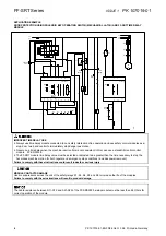
FIG 5. FUNCTIONAL DIAGRAM
a Width: 45 mm 1.77 in.
b Height: 74 mm 2.91 in.
c Depth: 121 mm 4.76 in.
Содержание SYA14 Series
Страница 2: ...2 107031 23 EN FR26 GLO 1199 Printed in France This page has been left intentionally blank ...
Страница 6: ...6 107031 23 EN FR26 GLO 1199 Printed in France This page has been left intentionally blank ...
Страница 26: ...26 107031 23 EN FR26 GLO 1199 Printed in France This page has been left intentionally blank ...
Страница 62: ...62 107031 23 EN FR26 GLO 1199 Printed in France This page has been left intentionally blank ...
Страница 70: ...70 107031 23 EN FR26 GLO 1199 Printed in France This page has been left intentionally blank ...
Страница 76: ...76 107031 23 EN FR26 GLO 1199 Printed in France This page has been left intentionally blank ...
Страница 78: ...78 107031 23 EN FR26 GLO 1199 Printed in France This page has been left intentionally blank ...
Страница 79: ...107031 23 EN FR26 GLO 1199 Printed in France 79 8 CE Declaration of Conformity ...
Страница 80: ...80 107031 23 EN FR26 GLO 1199 Printed in France This page has been left intentionally blank ...
Страница 84: ......
Страница 158: ......
Страница 160: ......
Страница 161: ...For application help call 1 800 537 6945 Honeywell MICRO SWITCH Sensing and Control 80 ...
Страница 165: ...3 107022 14 EN FR26 GLO 0100 Printed in Germany This page has been left intentionally blank ...
Страница 201: ...39 107022 14 EN FR26 GLO 0100 Printed in Germany This page has been left intentionally blank ...
Страница 205: ...43 107022 14 EN FR26 GLO 0100 Printed in Germany This page has been left intentionally blank ...
Страница 207: ...45 107022 14 EN FR26 GLO 0100 Printed in Germany This page has been left intentionally blank ...
Страница 208: ...107022 14 EN FR26 GLO 0100 Printed in Germany 46 9 Declaration of Conformity ...
Страница 219: ...11 107006 11 EN FR26 GLO 0300 Printed in Germany This page has been left intentionally blank ...
Страница 229: ...21 107006 11 EN FR26 GLO 0300 Printed in Germany This page has been left intentionally blank ...
Страница 257: ...49 107006 11 EN FR26 GLO 0300 Printed in Germany This page has been left intentionally blank ...
Страница 260: ...107006 11 EN FR26 GLO 0300 Printed in Germany 52 9 3 Declaration of conformity ...
Страница 263: ...PK 107007 1 EN FR26 GLO 298 Printed in France Safety Mat Installation Manual FF SM Series Safety Mat PK 107007 Issue 1 ...
Страница 264: ...ii Honeywell PK 107007 01 EN FR26 GLO 0298 Printed in France For application help see Warranty Information ...
Страница 340: ...Safety Perimeter Guarding Installation Manual FF SPS4 Series Safety Perimeter Guarding ...
Страница 536: ...2 107004 15 EN FR26 ROW 0899 Printed in France This page has been left intentionally blank ...
Страница 538: ...4 107004 15 EN FR26 ROW 0899 Printed in France This page has been left intentionally blank ...
Страница 542: ...107004 15 EN FR26 ROW 0899 Printed in France 8 This page has been left intentionally blank ...
Страница 620: ...86 107004 15 EN FR26 ROW 0899 Printed in France This page has been left intentionally blank ...
Страница 624: ...90 107004 15 EN FR26 ROW 0899 Printed in France This page has been left intentionally blank ...
Страница 626: ...92 107004 15 EN FR26 ROW 0899 Printed in France This page has been left intentionally blank ...
Страница 627: ...107004 15 EN FR26 ROW 0899 Printed in France 93 8 CE Declaration of Conformity ...
Страница 628: ...94 107004 15 EN FR26 ROW 0899 Printed in France This page has been left intentionally blank ...


