MICRO SWITCH Maintained Cable Pull limit Switch
PK 8156 0
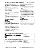
Figure 3: Typical Single Head Switch Installation
Figure 4: Typical Duplex Head Switch Installation
SWITCH MOUNTING, WIRING AND SEALING
Step 1 - Ensure you have the following:
l
Switch.
l
(2) #10 - 32 UNF screws.
l
#14 - #16 AWG stranded or #16 - #18 AWG solid
wire.
Step 2 - Mount switch:
l
Single head: Mount using (2) #10-32 UNF
screws from either front or back of switch.
Ensure a minimum of four threads of
engagement. Torque to 43-52 in.-lb (4.9-5.9 N-
W .
l
Duplex head: Mount using (2) #10-32 UNF
screws through mounting feet on left and right of
switch enclosure. Ensure a minimum of four
threads of engagement. Torque to 43-52 in.-lb
(4,9-5,9 N-m).
For application help: call 1-800-537-6945
Step 3 - Wire switch:
l
Connect stranded or solid wire to switch's
pressure type connector terminals. (Refer to
circuit diagram on switch housing. Diagram
depicts switch contacts when cable is at proper
tension.) Torque terminal screws and ground
screw to 7-9 in.-lb (0,8-1 N-m).
Step 4 - Seal conduit connection:
l
Seal with Teflon tape or pipe dope. If connector
is used to secure cable to enclosure, torque
connector to 16-19 in. lb (1,8-2,2 N-m).
IMPROPER SYSTEM PERFORMANCE
l
Ensure the attendant circuitry is such that only
the momentary interruption of the control circuit
cable pull contacts is required to open and hold
open the control circuit until such time as both
the cable pull switch and the attendant circuitry
are manually reset.
l
The user is SOLELY RESPONSIBLE for
determining the appropriate level of risk
warranting this type of circuitry.
l
Maintained Cable Pull Limit Switches must be
installed in a fashion that complies with all codes
and standards that are applicable to the particular
application of the device.
l
Failure to comply with these instructions could
result in death or serious injury.
ACTUATING CABLE INSTALLATION
Step 1 - Ensure you have the following
(Figures
3 and 4):
l
Plastic coated aircraft cable 1/8 in. (3,18 mm) to
3/16 in. (4,76 mm) dia. Use a distinctive color,
such as red, to differentiate actuating cable from
other wires or cables in the area.
l
Thimbles, U-bolt clamps.
Cable supports (eyebolts).
Honeywell
l
MICRO SWITCH Sensing and Control
2
Содержание SYA14 Series
Страница 2: ...2 107031 23 EN FR26 GLO 1199 Printed in France This page has been left intentionally blank ...
Страница 6: ...6 107031 23 EN FR26 GLO 1199 Printed in France This page has been left intentionally blank ...
Страница 26: ...26 107031 23 EN FR26 GLO 1199 Printed in France This page has been left intentionally blank ...
Страница 62: ...62 107031 23 EN FR26 GLO 1199 Printed in France This page has been left intentionally blank ...
Страница 70: ...70 107031 23 EN FR26 GLO 1199 Printed in France This page has been left intentionally blank ...
Страница 76: ...76 107031 23 EN FR26 GLO 1199 Printed in France This page has been left intentionally blank ...
Страница 78: ...78 107031 23 EN FR26 GLO 1199 Printed in France This page has been left intentionally blank ...
Страница 79: ...107031 23 EN FR26 GLO 1199 Printed in France 79 8 CE Declaration of Conformity ...
Страница 80: ...80 107031 23 EN FR26 GLO 1199 Printed in France This page has been left intentionally blank ...
Страница 84: ......
Страница 158: ......
Страница 160: ......
Страница 161: ...For application help call 1 800 537 6945 Honeywell MICRO SWITCH Sensing and Control 80 ...
Страница 165: ...3 107022 14 EN FR26 GLO 0100 Printed in Germany This page has been left intentionally blank ...
Страница 201: ...39 107022 14 EN FR26 GLO 0100 Printed in Germany This page has been left intentionally blank ...
Страница 205: ...43 107022 14 EN FR26 GLO 0100 Printed in Germany This page has been left intentionally blank ...
Страница 207: ...45 107022 14 EN FR26 GLO 0100 Printed in Germany This page has been left intentionally blank ...
Страница 208: ...107022 14 EN FR26 GLO 0100 Printed in Germany 46 9 Declaration of Conformity ...
Страница 219: ...11 107006 11 EN FR26 GLO 0300 Printed in Germany This page has been left intentionally blank ...
Страница 229: ...21 107006 11 EN FR26 GLO 0300 Printed in Germany This page has been left intentionally blank ...
Страница 257: ...49 107006 11 EN FR26 GLO 0300 Printed in Germany This page has been left intentionally blank ...
Страница 260: ...107006 11 EN FR26 GLO 0300 Printed in Germany 52 9 3 Declaration of conformity ...
Страница 263: ...PK 107007 1 EN FR26 GLO 298 Printed in France Safety Mat Installation Manual FF SM Series Safety Mat PK 107007 Issue 1 ...
Страница 264: ...ii Honeywell PK 107007 01 EN FR26 GLO 0298 Printed in France For application help see Warranty Information ...
Страница 340: ...Safety Perimeter Guarding Installation Manual FF SPS4 Series Safety Perimeter Guarding ...
Страница 536: ...2 107004 15 EN FR26 ROW 0899 Printed in France This page has been left intentionally blank ...
Страница 538: ...4 107004 15 EN FR26 ROW 0899 Printed in France This page has been left intentionally blank ...
Страница 542: ...107004 15 EN FR26 ROW 0899 Printed in France 8 This page has been left intentionally blank ...
Страница 620: ...86 107004 15 EN FR26 ROW 0899 Printed in France This page has been left intentionally blank ...
Страница 624: ...90 107004 15 EN FR26 ROW 0899 Printed in France This page has been left intentionally blank ...
Страница 626: ...92 107004 15 EN FR26 ROW 0899 Printed in France This page has been left intentionally blank ...
Страница 627: ...107004 15 EN FR26 ROW 0899 Printed in France 93 8 CE Declaration of Conformity ...
Страница 628: ...94 107004 15 EN FR26 ROW 0899 Printed in France This page has been left intentionally blank ...


