EN 60947-5-1-3
pending
Issue 2
PK 80086
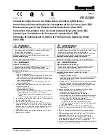
Installation Instructions for the Global Safety Limit Switch (GSS Series)
Instrucciones de instalación para los interruptores de fin de carrera (serie GSS)
Einbauanweisungen für den Sicherheits-Positionsschalter (Serie GSS)
Instructions d’installation du fin de course standard de sécurité (série GSS)
Istruzioni per l'installazione del finecorsa di sicurezza (Serie GSS)
Instruções de Instalação para o Switch de Fim de Curso de Segurança Global
(Série GSS)
Sensing and Control
WARNING
IMPROPER INSTALLATION
•
Consult with local safety agencies and their requirements when
designing a machine-control link, interface, and all control
elements that affect safety.
•
Strictly adhere to all installation instructions.
Failure to comply with these instructions could result in
death or serious injury.
MOUNT, WIRE AND SEAL SWITCH
WARNING
IMPROPER OPERATION
•
Ensure switch actuator achieves sufficient travel for positive
opening of normally closed (NC) contacts to occur.
Failure to comply with these instructions could result in
death or serious injury.
1. Refer
to:
•
Page 3 for adjustments.
•
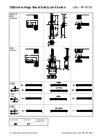
Page 4 for EN 50041 wiring configurations for each switch
code. (Ag=silver contacts, Au=gold-plated contacts)
•
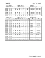
Pages 5 and 6 for specific travel distances for each switch
code, and specifications.
•
Page 7 proper application of limit switches, and switch
mounting dimensions.
2. Perform adjustments (if desired). Use the TORX
tamper-
resistant bit (included):
•
Head orientation (Figure 1).
•
Actuation direction (Figure 2).
•
Side rotary switches with 90
°
positive drive levers (catalog
listings ending in A1A, A1B, A5A, A5B) (Figure 3):
−
Ensure flats of switch shaft engage groove in actuator
lever.
−
Tighten locking screw (A) until tab (B) no longer moves.
3. Mount switch using four M5 or #10 screws. Torque screws to
4,9-5,9 N m (43-52 in lb).
4. Remove tamper-proof screws on cover plate.
5. Connect stranded wire (0,75 mm
2
-2,5 mm
2
, 18-14 AWG) or
solid wire (0,75 mm
2
to 1,5 mm
2
, 18-16 AWG) to connector
terminals (use 90
°
C wire when ambient temperature is over
75
°
C). Torque switch terminal screws to 0,8-1,0 N m
(7-9 in lb).
6. Seal conduit opening according to instructions in PK 80112.
7. Reassemble
cover
plate
ADVERTENCIA
INSTALACIÓN INCORRECTA
•
Consulte las normas de seguridad y sus requisitos al realizar el
diseño del enlace de control de una máquina, la interfaz, y los
elementos de control que afecten a la seguridad.
•
Siga estrictamente todas las instrucciones para la instalación.
El incumplimiento de estas recomendaciones puede
ocasionar lesiones graves o peligro de muerte.
MONTAJE, CABLEADO Y SELLADO DEL INTERRUPTOR
ADVERTENCIA
FUNCIONAMIENTO INCORRECTO
•
Asegúrese que el actuador del interruptor tenga la suficiente
carrera para que se produzca la apertura positiva de los
contactos normalmente cerrados (NC).
El incumplimiento de estas recomendaciones puede
ocasionar lesiones graves o peligro de muerte.
1. Consulte:
•
la página 3 para los ajustes
•
la página 4 para las configuraciones de cableado EN 50041
para cada código de interruptor. (Ag=contactos de plata,
Au=contactos de oro)
•
las páginas 5 y 6 para las distancias de carrera específicas
de cada código de interruptor y las especificaciones.
•
la página 7 para la correcta aplicación de los interruptores
final de carrera y las dimensiones de montaje del
interruptor.
2. Realice los ajustes (si fuera necesario). Utilice el tornillo
TORX
resistente a alteraciones (incluido):
•
Orientación del cabezal (véase la figura 1).
•
Dirección del accionamiento (véase la figura 2).
•
Interruptores de rotación lateral con palancas de impulsión
positiva de 90º (las referencias del catálogo que terminen
en A1A, A1B, A5A, A5B) (véase la figura 3):
−
Asegúrese de que las caras del eje del interruptor
enganchen la ranura de la palanca del actuador.
−
Ajuste el tornillo de apriete (A) hasta que la lengüeta (B)
deje de moverse.
3. Para montar el interruptor, utilice cuatro tornillos M5 o del
número 10. Ajuste los tornillos hasta
4,9-5,9 N m (43-52 pulg.
lb).
4. Retire los tornillos garantizados contra toda alteración de la
tapa.
5. Conecte cable trenzado (0,75 mm
2
-2,5 mm
2
, 18-14 AWG) o
cable sólido (0,75 mm
2
a 1,5 mm
2
, 18-16 AWG) a los
terminales del conector (utilice cable de 90
°
C cuando la
temperatura ambiente supere los 75
°
C). Ajuste los tornillos
de los terminales hasta 0,8-1,0 N m (7-9 pulg. lb).
6. Selle el conducto de entrada según las instrucciones en PK 80112
7. Vuelva a colocar en su sitio la tapa.
Содержание SYA14 Series
Страница 2: ...2 107031 23 EN FR26 GLO 1199 Printed in France This page has been left intentionally blank ...
Страница 6: ...6 107031 23 EN FR26 GLO 1199 Printed in France This page has been left intentionally blank ...
Страница 26: ...26 107031 23 EN FR26 GLO 1199 Printed in France This page has been left intentionally blank ...
Страница 62: ...62 107031 23 EN FR26 GLO 1199 Printed in France This page has been left intentionally blank ...
Страница 70: ...70 107031 23 EN FR26 GLO 1199 Printed in France This page has been left intentionally blank ...
Страница 76: ...76 107031 23 EN FR26 GLO 1199 Printed in France This page has been left intentionally blank ...
Страница 78: ...78 107031 23 EN FR26 GLO 1199 Printed in France This page has been left intentionally blank ...
Страница 79: ...107031 23 EN FR26 GLO 1199 Printed in France 79 8 CE Declaration of Conformity ...
Страница 80: ...80 107031 23 EN FR26 GLO 1199 Printed in France This page has been left intentionally blank ...
Страница 84: ......
Страница 158: ......
Страница 160: ......
Страница 161: ...For application help call 1 800 537 6945 Honeywell MICRO SWITCH Sensing and Control 80 ...
Страница 165: ...3 107022 14 EN FR26 GLO 0100 Printed in Germany This page has been left intentionally blank ...
Страница 201: ...39 107022 14 EN FR26 GLO 0100 Printed in Germany This page has been left intentionally blank ...
Страница 205: ...43 107022 14 EN FR26 GLO 0100 Printed in Germany This page has been left intentionally blank ...
Страница 207: ...45 107022 14 EN FR26 GLO 0100 Printed in Germany This page has been left intentionally blank ...
Страница 208: ...107022 14 EN FR26 GLO 0100 Printed in Germany 46 9 Declaration of Conformity ...
Страница 219: ...11 107006 11 EN FR26 GLO 0300 Printed in Germany This page has been left intentionally blank ...
Страница 229: ...21 107006 11 EN FR26 GLO 0300 Printed in Germany This page has been left intentionally blank ...
Страница 257: ...49 107006 11 EN FR26 GLO 0300 Printed in Germany This page has been left intentionally blank ...
Страница 260: ...107006 11 EN FR26 GLO 0300 Printed in Germany 52 9 3 Declaration of conformity ...
Страница 263: ...PK 107007 1 EN FR26 GLO 298 Printed in France Safety Mat Installation Manual FF SM Series Safety Mat PK 107007 Issue 1 ...
Страница 264: ...ii Honeywell PK 107007 01 EN FR26 GLO 0298 Printed in France For application help see Warranty Information ...
Страница 340: ...Safety Perimeter Guarding Installation Manual FF SPS4 Series Safety Perimeter Guarding ...
Страница 536: ...2 107004 15 EN FR26 ROW 0899 Printed in France This page has been left intentionally blank ...
Страница 538: ...4 107004 15 EN FR26 ROW 0899 Printed in France This page has been left intentionally blank ...
Страница 542: ...107004 15 EN FR26 ROW 0899 Printed in France 8 This page has been left intentionally blank ...
Страница 620: ...86 107004 15 EN FR26 ROW 0899 Printed in France This page has been left intentionally blank ...
Страница 624: ...90 107004 15 EN FR26 ROW 0899 Printed in France This page has been left intentionally blank ...
Страница 626: ...92 107004 15 EN FR26 ROW 0899 Printed in France This page has been left intentionally blank ...
Страница 627: ...107004 15 EN FR26 ROW 0899 Printed in France 93 8 CE Declaration of Conformity ...
Страница 628: ...94 107004 15 EN FR26 ROW 0899 Printed in France This page has been left intentionally blank ...


