61
3.5.4 Connectors
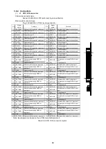
The input and output signals of this module are as follows.
Connector
Name
Signal
name
IN/
OUT
Voltage
Explanation
Remarks
J1
J2
Connector for
axis 1 (2)
pulse-motor
(Motor1/Motor2)
signals
CW
O
5V
Clockwise pulse
CCW
O
5V
Counterclockwise pulse
MF
O
5V
Excitation OFF
C/S
O
5V
Step angle switching
CD_INH
O
5V
Automatic current-down
prohibition
TIM
I
5V
Excitation timing input
J3
Sensor
connector
(Sensor)
+ELS
I
12 to 24V
(+) side end-limit input
Signals
described on
left:
-ELS
I
12 to 24V
(-) side end-limit input
one set for
each of the two
axes
DLS
I
12 to 24V
Deceleration sensor input
OLS
I
12 to 24V
Origin sensor input
Table 3.5-3 Connector input and output signals
(1)
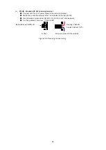
Connection configuration
Figure 3.5-3 Connection configuration
CN1
G9003
指令パルス CW
指令パルス CCW
MF
CD_INH
モ
ー
タ
ー
I
/
F
+ELS
- ELS
OLS
DLS
OUT
DIR
P 0
+EL
-EL
ORG
P2
P3
5V
5V
5V
5V
5V
TIM
E Z
5V
C/S
24V 24V
24V
24V
24V
指令パルス CW
指令パルス CCW
MF
CD_INH
モ
ー
タ
ー
I
/
F
OUT
DIR
P 0
P2
P3
5V
5V
5V
5V
5V
TIM
E Z
5V
C/S
G9003
SD
J
1
:M
ot
or1
J
2
:M
ot
or2
+ELS
- ELS
OLS
DLS
+EL
-EL
ORG
24V 24V
24V
24V
24V
SD
セ
ン
サ
ー
I
/
F
J
3
:Se
n
sor
ドライバー
ドライバー
HM-W200C
CN2
Command pulse
CW
M
o
to
r I/
F
Command pulse
CCW
Command pulse
CW
Command pulse
CCW
M
o
to
r I/
F
S
e
n
so
r I
/F
Driver
Driver
Содержание motionCAT HCPCI-MNT720M
Страница 1: ...Motion Network System motionCAT series User s Manual Introduction Hivertec inc http www hivertec co jp...
Страница 3: ......
Страница 12: ...1 Warnings and Precautions...
Страница 20: ...9 1 motionCAT Installation...
Страница 109: ...98 4 Installation Guide...
Страница 118: ...107 5 Device Driver Installation...
Страница 122: ...111 6 Trial Operation...
Страница 145: ...134 7 Accessories...
Страница 147: ...136 8 Glossary...
Страница 161: ...150 9 Connections to Drivers Supplied by Manufacturers...

