


44
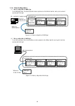
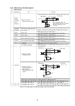
3.2.4 Module ID Setting
Set the module ID (MID) of the modules within the slave.
The MID of each module stacked within the slave is automatically assigned based on the MID set in the rotary
switch for module ID setting. The MID of each module is given by incrementing the MID set to the module
stacked next to the communication module by 1 for each displacement in the stacking position from that
module.
Some modules have only one rotary switch for module ID setting while others have two.
In those having two rotary switches for module ID setting, the first MID for the slave can be arbitrarily set in
the range of 00 to 3C (HEX).
In those having only one rotary switch for module ID setting, set it in the range of 0 to 8. The first MID for the
slave will be 8 times the number set with the switch.
In either case, make sure the set MID is unique within the same line. With modules that have two rotary
switches for MID setting, be especially careful when using multiple slaves as the first MID can be set
arbitrarily.
MID numbers may be non-consecutive. Furthermore, MIDs do not need to increase or decrease in
accordance with the order in which slaves are connected. The following figure shows an example of module
ID setting with the rotary switch(es).
Figure 3.2-3 Module ID settings
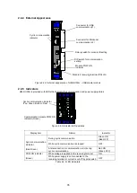
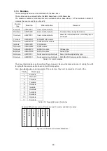
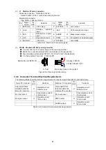
3.2.5 Communication Settings Switch
• Termination (TR-on) Turn this ON only when the slave is on the very end of the LAN cable.
• Communication cable disconnection detection (DBG) Normally ON (communication cable disconnection detection enabled).
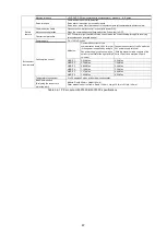
• Communication speed (SPD0, SPD1) Set the same communication speed as the one configured on the master board
Off position
SPD0: Communication speed setting (Default is OFF: 20Mbps)
SPD1 Ditto
DBG: Communication cable disconnection detection enabled/disabled
(Default is ON: Communication cable disconnection detection enabled)
TR-on: Termination setting (Default is OFF: Not the last slave)
A.Top view
B. End view
Default settings: 1:off, 2:on, 3:off, 4:off (not the last slave, communication cable disconnection detection enabled, 20Mbps)
Figure 3.2-4 Communication settings switch
MID
0 1 2 3 4 5
SPD0
off
on
off
on
SPD1
off
off
on
on
Speed
(bps)
20M
10M
5M
2.5M
F
12
B
A
CDE
6 57
8
9
0
34
F
12
B
A
CDE
6 57
8
9
0
34
F
12
B
A
CDE
6 57
8
9
0
34
F
12
B
A
CDE
6 57
8
9
0
34
0
1
2
3
4
5
6 7
0
12
3
4
5 6 7
Communication module
MID rotary switches
(Setting '00' = MID: 00h)
Lower
Upper
SPD0
SPD1
Debug
Term
N
O
MID rotary switch
(Setting '2' = MID: 16 (10h))
With two rotary switches
With one rotary switch
The value set with MID rotary switches will be the MID of the first module.
Subsequent MIDs are assigned automatically. When connecting another slave in
addition to this one, the MID must be 6 or greater.
Communication module
MID
16
17 18
Содержание motionCAT HCPCI-MNT720M
Страница 1: ...Motion Network System motionCAT series User s Manual Introduction Hivertec inc http www hivertec co jp...
Страница 3: ......
Страница 12: ...1 Warnings and Precautions...
Страница 20: ...9 1 motionCAT Installation...
Страница 109: ...98 4 Installation Guide...
Страница 118: ...107 5 Device Driver Installation...
Страница 122: ...111 6 Trial Operation...
Страница 145: ...134 7 Accessories...
Страница 147: ...136 8 Glossary...
Страница 161: ...150 9 Connections to Drivers Supplied by Manufacturers...


