


52
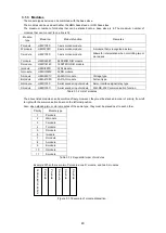
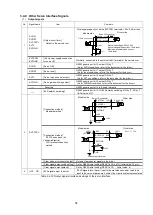
3.4.7 Command Pulse Output and Connection to Drivers
The following table shows the requirements for the command pulse output circuits.
No.
Signal name
Item
Contents
1
Command pulse
CWP, CWN
CCWP, CCWN
[Electrical condition]
1. Output element: Differential driver (26LS31 or equivalent)
2. Command pulse width: 50% duty width of command frequency
However, in the case of 2.4Kpps or less: 200μs width
In the case of 5Mpps or above: 30% duty width
2
CWP, CWN
CCWP, CCWN
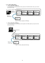
[Output format setting]
Initial value: RENV1 CW/CCW
Pulse
Set by G9003 initial setting (RENV1-b2 to b0)
[Output format: CW/CCW Pulse]
Output format specified by
RENV1
[Output format: Pulse/Direction]
Output format and direction level
specified by RENV1.
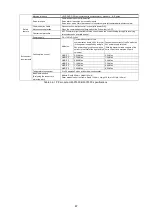
3
CWP, CWN
CCWP, CCWN
GND
[Driver connection method: via
differential input]
[Driver connection method: via
photocoupler input]
For a driver with single-ended
photocoupler
[Driver connection method: via
differential input photocoupler]
For a driver that ensures
differential connection to
photocoupler input
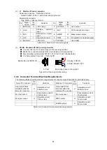
[Driver connection method: via
TTL input]
Note:
When using a motor driver that is not the differential input type, be especially careful about the speed
and the cable length.
A standard is 500Kpps (cable length: 3m or shorter) for drivers with single-ended type input photocouplers,
and 250Kpps (1m) for those with TTL input. Use twisted pair wires for signal lines. Also, check the
specifications for the connection to the motor driver controller in advance.
Table 3.4-10 Command pulse output circuits
0V
CCWP terminal
CCWN terminal
CWP terminal
CWN terminal
Direction signal output
Pulse train output
0V
0V
0V
0V
CWP terminal
CWN terminal
CCWP terminal
CCWN terminal
CWP terminal
CWN terminal
Driver side
Module side
(One side only shown)
Note: The GND levels must match between module and driver sides.
Note: The GND levels must match between module and driver
sides.
GND terminal
GND terminal
GND
GND
Ex5V
Ex5V
Module side
Driver side
CWP terminal
CWN terminal
CCWP terminal
GND terminal
GND terminal
CCWN terminal
GND terminal
+5V
Module side
Driver side
GND terminal
CWN terminal
(One side only shown)
Module side
Driver side
CWP terminal
CWN terminal
CCWP terminal
CCWN terminal
GND terminal
GND
GN
D
Note: The GND levels must
match between module
and driver sides.
Содержание motionCAT HCPCI-MNT720M
Страница 1: ...Motion Network System motionCAT series User s Manual Introduction Hivertec inc http www hivertec co jp...
Страница 3: ......
Страница 12: ...1 Warnings and Precautions...
Страница 20: ...9 1 motionCAT Installation...
Страница 109: ...98 4 Installation Guide...
Страница 118: ...107 5 Device Driver Installation...
Страница 122: ...111 6 Trial Operation...
Страница 145: ...134 7 Accessories...
Страница 147: ...136 8 Glossary...
Страница 161: ...150 9 Connections to Drivers Supplied by Manufacturers...


