


56
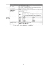
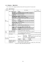
3.4.10 Machine Interface
No.
Signal name
Item
Contents
1
±ELS
DLS
OLS
[Input circuit form]
Input from the axis sensor
EXTPOW,
EXTGND
[Power supply connection for
sensor]
Connected to the sensor’s +24V, GND terminals.
2
±ELS
[Over-travel sensor signal]
Signal polarity is set by G9003 initial setting (RENV1-b9) (Initial value:
NC)
DLS
[Deceleration sensor signal]/
[Counter clear/ Counter latch]
See the next page, Note 2.
Signal polarity is set by G9003 initial setting (RENV1-b6) (Initial value:
NC)
OLS
[Sensor origin signal]
Signal polarity is set by G9003 initial setting (RENV1-b7) (Initial value:
NC)
Also, when using SVRDY, the mode register initial setting must be set to:
RMD-
b13 = ‘0’.
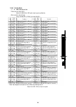
3
CMP
[Coordinate counter comparison
output]
For
further details, see “motionCAT series User’s Manual <Operation>”.
[Output circuit form]
4
SVBRK
[Brake release signal output]
See the previous section.
Table 3.4-14 Machine interface
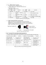
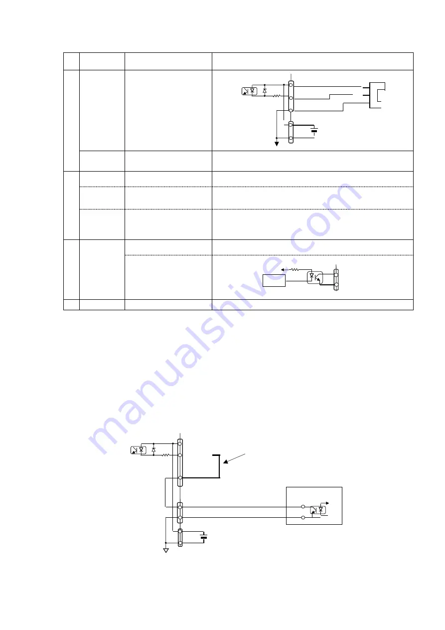
Note 1: SVRDY signal [Servo ready] / [PCS]
1. Twofold function is assigned to the SVRDY signal pin as follows:
(1)
The default setting is SVRDY signals. (The software setting must be: operation mode register RMD b13 = ‘0’)
(2) The other is PCS function. (The software setting must be: ope
ration mode register RMD b13 = ‘1’)
As for details on the function and operation, see “motionCAT series User’s Manual <Operation>”.
2. About cable wiring for the use of PCS function
PCS signals are input as sensor signals. Hence, connect the servo I/F connector SVRDY pin (32) to the
SVBRK pin (16).
Complete the cable wiring by connecting the PCS signals to the machine I/F connector SVBRK (6).
However, this will make it impossible to use brake release signals.
Figure 3.4-5 How to implement PCS
Connect within the connector.
Machine I/F connector
SVBRK (16)
Servo I/F connector
SVBRK (6)
Module side
+
+
+24
V
+24
V
+24
V
+24
V
GN
D
GN
D
EXTGND
EXTPOW
SVBRK (32)
-
-
PCS sensor output
4.7K
4.7K
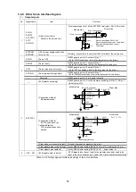
Module side
+24V
+24V
GND
EXTGND
EXTPOW
+/-ELS-OLS
Vcc
OUT
GND
4.4K
Machine I/F connector
Power supply terminal
Axis sensor
Module side
CMP
CMP
EXTGND
Содержание motionCAT HCPCI-MNT720M
Страница 1: ...Motion Network System motionCAT series User s Manual Introduction Hivertec inc http www hivertec co jp...
Страница 3: ......
Страница 12: ...1 Warnings and Precautions...
Страница 20: ...9 1 motionCAT Installation...
Страница 109: ...98 4 Installation Guide...
Страница 118: ...107 5 Device Driver Installation...
Страница 122: ...111 6 Trial Operation...
Страница 145: ...134 7 Accessories...
Страница 147: ...136 8 Glossary...
Страница 161: ...150 9 Connections to Drivers Supplied by Manufacturers...


