


24
a
b
c
d
e
1
5
11
15
20
25
Di4/Do4
J1
J2
J3
Line1
Line2
F1
2
B
A
C
D
E
6
5
789
0
3
4
BDID
ON
ON
2.5Mbps
OFF
ON
5Mbps
ON
OFF
10Mbps
OFF
OFF
20Mbps
SPD0 SPD1
SW1
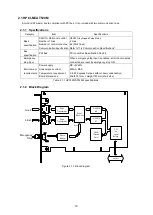
2.2.3 Board Settings
The following diagram shows HCPCI-MNT720M settings to be configured. Configure the board ID and
communication speed settings.
Figure 2.2-2 Setting positions
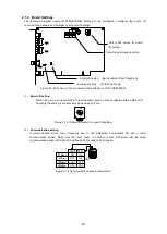
(1)
Board ID setting
When using two or more motionCAT master boards, each must be configured with a different ID.
Changing the setting is unnecessary when using only one board.
Figure 2.2-3 Rotary DIP switch for board ID setting
(2)
Communication setting
If communication errors occur frequently due to the installation environment etc, use a lower
communication speed. Make sure that each slave to connect is also configured with the same
communication speed. Normally, this setting does not need to be changed.
Figure 2.2-4 Communication speed setting switch
F1
2
B
A
C
DE
6
5
789
0
3
4
BDID
ON
ON
2.5Mbps
OFF
ON
5Mbps
ON
OFF
10Mbps
OFF
OFF
20Mbps
SPD0 SPD1
SW1
Rotary DIP switch for board
ID setting
Communication
speed switch
Содержание motionCAT HCPCI-MNT720M
Страница 1: ...Motion Network System motionCAT series User s Manual Introduction Hivertec inc http www hivertec co jp...
Страница 3: ......
Страница 12: ...1 Warnings and Precautions...
Страница 20: ...9 1 motionCAT Installation...
Страница 109: ...98 4 Installation Guide...
Страница 118: ...107 5 Device Driver Installation...
Страница 122: ...111 6 Trial Operation...
Страница 145: ...134 7 Accessories...
Страница 147: ...136 8 Glossary...
Страница 161: ...150 9 Connections to Drivers Supplied by Manufacturers...


