


21
Line2
Line1
EMG
(3)
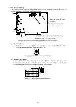
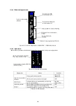
Emergency stop setting
Cut the short pin with a pincher to enable emergency stop input. Also configure the "Emergency stop
12V/24V switching" switch to the voltage of the external power to use for emergency stop input.
Emergency stop power-voltage switching switch
When using 24V: OFF
When using 12V: ON
Cut short pin to enable emergency stop input
Figure 2.1-5 Emergency stop setting
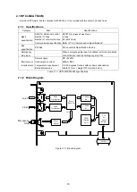
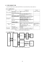
2.1.4 Master Board Panel Layout
Figure 2.1-6 Connector positions on HPCI-MCAT520M
2.1.5 Connector Signal Table
(1)
J1 Connector for emergency stop input (EMG)
Pin
Signal name
1
Emergency stop signal (+12V or +24V input)
2
GND
Omron:
MC1,5/2-G-3,81
Auxiliary harness: MC1,5/2-ST-3,81
Table 2.1-2 Pin assignment of emergency stop input part (J1)
GND
Lit during cyclic communication (GREEN)
LINE2 (J3)
LINE1 (J2)
Emergency
stop signal
(+24V)
EMG (J1)
Lit during communication error (RED)
Содержание motionCAT HCPCI-MNT720M
Страница 1: ...Motion Network System motionCAT series User s Manual Introduction Hivertec inc http www hivertec co jp...
Страница 3: ......
Страница 12: ...1 Warnings and Precautions...
Страница 20: ...9 1 motionCAT Installation...
Страница 109: ...98 4 Installation Guide...
Страница 118: ...107 5 Device Driver Installation...
Страница 122: ...111 6 Trial Operation...
Страница 145: ...134 7 Accessories...
Страница 147: ...136 8 Glossary...
Страница 161: ...150 9 Connections to Drivers Supplied by Manufacturers...


