background image

14.2  External I/O

383

14

Chapter 14

  External Control

2

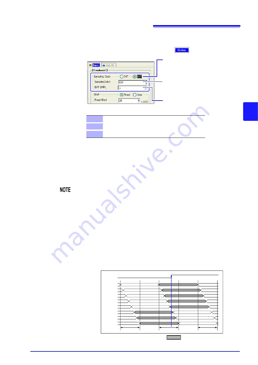
In the Status Settings screen (Memory Function), make the following external
sampling settings.

3

Input HIGH level (3.0 to 5.0 V) and LOW level (0 to 0.8 V) pulse waves or rectan-
gular waves to the EXT.SMPL terminal.

Data is sampled on the rising edge, falling edge, or both edges of the input
waveform. Note that the sampling frequency is limited by the selected edge or
edges. ("Supported external sampling pulse widths" (p. 382))

Sample on rising edge.

Sample on falling edge (default setting).

&

Sample on both rising and falling edges.

(To open the screen: Press the 

SET 

key 

 Select 

 with the 

SUB MENU

 key

Status Settings screen)

Set Sampling clock to 

[EXT]

.

Set the number of data points to display per
division on the horizontal axis (time axis).
Input range: 10 to 1000 (Default setting:
100)

See

"Entering Numbers" (p. 65)

Select the input waveform sampling meth-
od. (This can also be set in the Ext Term
Settings Screen.

• When a sampling signal of 5 MHz or greater is input, trigger points are

delayed by 1 sample.

• It is recommended that the Roll Mode function be set to [On] when the exter-

nal sampling input signal is 100 kHz or lower (p. 102). When the Roll Mode
function is set to [Off] or [Auto], external sampling data is collected and saved
in memory after external sampling signals (rising, falling, and both rising and
falling) are input 32 times.

When the 8958 16-Ch Scanner Unit is installed

• Input sampling input signals of 100 kHz or lower. Signals higher than 100 kHz

cannot be sampled.

• During scanning, if they overlap with the external sampling frequency, chan-

nels where scanning is finished exist at the same time as channels where
scanning is not finished. Data may be sampled according to the timing shown
in the figure below.

CH1 Dn-1

EXT.SMPL

8958

CH1

CH2

CH3

CH4

CH5

CH6

CH7

CH8

CH1 Dn

CH2 Dn-1

CH2 Dn

CH3 Dn-1

CH3 Dn

CH4 Dn-1

CH4 Dn

CH5 Dn-1

CH5 Dn

CH6 Dn-1

CH6 Dn

CH7 Dn-1

CH7 Dn

CH8 Dn-1

CH8 Dn

Scanning operation

Scanning operation

Scanning operation

Sampled data

External sampling timing

Содержание 8860-50

Страница 1: ...50 8861 50 MEMORY HiCORDER Instruction Manual 8861 50 MEMORY HiCORDER 8860 50 October 2013 Revised edition 7 8860B983 07 13 10H This manual describes the instrument s functions and operations in deta...

Страница 2: ......

Страница 3: ...5 2 Channel Settings Screen 32 2 5 3 Trigger Settings Screen 35 2 5 4 Sheet Settings Screen 36 2 5 5 Memory Division Settings Screen 37 2 5 6 Numerical Calculation Num Calc Settings Screen 38 2 5 7 W...

Страница 4: ...atic Range Setting Auto Ranging Function 74 3 3 6 Starting and Stopping Measurement 76 3 3 7 Disabling Key Operations Key Lock Function 78 Chapter 4 Measurement Configuration Settings __________79 4 1...

Страница 5: ...ombining Logic AND OR for Multiple Trigger Sources 139 6 5 Pre Trigger Settings 140 6 5 1 Setting the Trigger Start Point Pre Trigger 140 6 5 2 Setting Trigger Acceptance Trigger Priority 143 6 6 Sett...

Страница 6: ...7 2 5 Setting Waveform Scrolling Orientation 180 7 2 6 Assigning Display Channels to Graphs Analog Channels 181 7 3 Displaying Logic Waveforms 183 7 3 1 Setting the Waveform Display 184 7 3 2 Setting...

Страница 7: ...alues 221 8 14 Searching a Waveform 222 8 14 1 Searching by Trigger Criteria 223 8 14 2 Searching by Time 228 8 14 3 Searching for Peaks 229 8 15 Inserting and Searching for Event Marks on a Waveform...

Страница 8: ...ving SAVE Key 285 11 3 9 Automatically Saving Display Images 287 11 3 10Optionally Selecting Display Screens Saving SAVE Key 289 11 3 11Saving an Event Mark List 290 11 4 Loading Data 291 11 4 1 Selec...

Страница 9: ...reen Display Settings 350 13 1 1 Selecting the Grid Type 350 13 1 2 Displaying or Hiding Comments 351 13 1 3 Selecting the Time Value Display 352 13 1 4 Displaying Zero Position 352 13 2 Making Key Op...

Страница 10: ...378 14 2 2 Trigger Output TRIG OUT CAL 380 14 2 3 External Sampling EXT SMPL 382 14 2 4 Synchronized Sampling Output SYNC OUT 384 14 2 5 GO NG Evaluation Output GO EXT OUT1 NG EXT OUT2 387 14 2 6 Ext...

Страница 11: ...s Memory Division function A 38 Appendix 2 6 Compatible External Printers A 42 Appendix 2 7 Scaling Method When Using Strain Gauges A 43 Appendix 2 8 Keyboard Assignment Table A 44 Appendix 3 Terminol...

Страница 12: ...Contents x...

Страница 13: ...ent Operations Basic Settings 4 1 Selecting the Function p 81 4 2 Setting Measurement Configuration Status Settings Screen p 86 5 1 Analog Channel Settings p 116 6 3 Setting the Trigger Mode p 138 Rec...

Страница 14: ...alues p 202 Saving and Loading Data Chapter 11 Saving Loading Data Managing Files p 261 Printing Data Chapter 12 Printing p 313 Communicating with this Instru ment from a Personal Computer Chapter 4 C...

Страница 15: ...es the optional input modules relat ed cable connection procedures and their settings and specifications 3 Instruction Manual This document To obtain setting details this Manual describes details of t...

Страница 16: ...e to the instrument Indicates advisory items related to performance or correct operation of the instrument Indicates a prohibited action p Indicates the location of reference information Indicates qui...

Страница 17: ...perated with a mouse most of the operating descriptions in this manual involve only the operating keys Selectable functions Screen opening procedure See 2 2 Screen Organization p 17 Setting procedure...

Страница 18: ...Reading this Manual 6...

Страница 19: ...put modules support recording of many types of parameters Model 8956 Analog Unit Provides 20 MS s waveform recording with 12 bit resolution Model 8957 High Resolution Unit Provides 2 MS s waveform rec...

Страница 20: ...ch slope voltage sag logic pattern and timer triggers See Chapter 6 Trigger Settings p 135 By setting the measurement unit name and physical value per volt of input sig nal measurements are converted...

Страница 21: ...optional Flash ATA Cards hard disks and and USB memory device Two PC Card slots are provided so an interface card and a Flash ATA card can be used at the same time See 11 1 Storage Media p 262 An HTT...

Страница 22: ...rol Synchronous operation p 375 Measurement Input Modules 1 3 Logic Probes 1 3 Model 9327 Logic Probe Model MR9321 01 Logic Probe Model 9320 01 Logic Probe Connection Cables 3 Voltage Measurement Mode...

Страница 23: ...g by the CPU measurement data is stored in memory for display on the LCD or output to the printer Data can be saved to and reloaded from a PC Card or other external storage media Storage Control Stora...

Страница 24: ...1 3 Interconnection and Block Diagrams 12...

Страница 25: ...wer On state Flashes red Standby state To cancel Standby state Press the STANDBY ON key again See 3 6 Turning the Power On and Off in the Quick Start Manual PRINT key Prints measurement data stored in...

Страница 26: ...screen GUI Graphical User Interface Press a key to select its corresponding choice F keys indicates all of the F1 to F8 keys collectively See 3 3 2 To Change a Setting p 63 FUNCTION MODE key Alters th...

Страница 27: ...nd hold the CURSOR keys for three seconds to disable key operations Key Lock function To cancel key lock hold the keys again for three seconds See 3 3 7 Disabling Key Operations Key Lock Function p 78...

Страница 28: ...f the vertical axis and whether or not they are displayed available on the Waveform and Channel Settings screens To set the measurement range turn the inner RANGE knob To change the waveform display p...

Страница 29: ...PAGE Key Operations p 357 Settings Screen p 27 SET Displays the setting screen for measurement data for making settings relating to the display of measurement configuration Waveform screen and calcul...

Страница 30: ...s Use to record relatively fast signals with periods from s to minutes Recorder Function Recommended for long term measurements Records waveforms at slow speeds Use to record relatively slow signals w...

Страница 31: ...ting Items and Choices p 21 Measurement configuration and trigger criteria set tings can be changed These can be changed while measuring Press the SUB MENU keys to select the items to change Clock Sho...

Страница 32: ...dd a waveform comment 5 2 Adding Comments p 118 13 1 2 Displaying or Hid ing Comments p 351 Displayed Sheet No Number of Waveform Acquisitions Unit Module and Channel Nos 1 1 Unit 1 Channel 1 Numerica...

Страница 33: ...mpression of the whole waveform You can select Mag to display the whole waveform on one screen Trigger Mode Setting p 138 Sets subsequent triggering criteria after a measurement operation is finished...

Страница 34: ...g Item Category See Chapter 1 Numerical Calculation Functions in the Analysis and Communication Supplement Changes do not affect the measurement currently in progress Calculation Type Numerical Calcul...

Страница 35: ...M display REC display MEM display See Chapter 10 Long Term Monitoring and Instantaneous Recording p 253 Displayed Data Type Loading data Loaded Length Magnification Setting Item Category Displayed Dat...

Страница 36: ...ady Idle state Printing Printing in progress Saving Saving in progress Auto Ranging Automatic range selection in progress Complete Finished automatic range selection File Name Name of loaded file 2 St...

Страница 37: ...d raised error 1 Out of Paper error 1 Internal Storage Media Hard drive installed PC card Slot 1 PC card Slot 2 Internal Storage Media when internal drive Model 9718 50 HD Unit installed FD Drive LAN...

Страница 38: ...erations This is the same as the Settings screen 8 6 Monitoring Input Levels Level Monitor p 199 SET Mode FN Mode MACRO Mode 3 3 5 Automatic Range Setting Auto Ranging Function p 74 5 7 Setting Input...

Страница 39: ...set tings Trigger Settings Screen p 35 Trigger criteria settings Sheet Settings Screen p 36 Waveform screen display related settings Memory Division Mem Div Settings Screen p 37 Memory Division relate...

Страница 40: ...of an external signal input Timebase 2 Settings p 94 Make these settings to mea sure with two sampling rates or when using the Model 8958 16 Ch Scanner Unit together with another input module Memory F...

Страница 41: ...y waveform p 90 Set the timebase of the hori zontal axis time per division The sampling rate changes ac cordingly Set the timebase horizontal axis and recording length recording duration Recording Len...

Страница 42: ...Save Destination Info Usable settings are limited by the available space on the save destination Recording Length Settings Set the length recording dura tion to record each time data is acquired or s...

Страница 43: ...d to newly ac quired data or to a pre existing waveform Memory wave form Window Function Settings Selects a window function and correction for acquiring input signals Peak Value Display Setting Select...

Страница 44: ...st p 129 Input Module Settings p 116 Set the input channels for the installed input modules See Chapter 3 Input Channel Settings in the Input Module Guide These settings are also avail able on the All...

Страница 45: ...ween channels Execute Zero Adjust and Auto Balance Executes for all channels at once Details Input Module Guide Input Channel Settings List Setting Procedures p 130 Setting Contents p 116 Adjusts the...

Страница 46: ...ition and mag nification on the vertical axis can be freely set The variable function can be set on or off for each channel Setting Procedures p 132 Setting Contents p 215 Logic Page Input enable disa...

Страница 47: ...et timing when desired to apply a trigger within a specified period External Trigger Settings p 166 Set this to accept triggering from a signal input on the Ex ternal Trigger terminal Trigger Mode Set...

Страница 48: ...form scrolling direction p 180 Split screen and display pat tern p 178 function dependent Assigning Channels to Sheets p 174 Assign which channel is to be displayed on each sheet and waveform display...

Страница 49: ...ws memory block numbers and the current position This display can be switched to a list Recording Length Setting Set the length recording dura tion to record each time a block is acquired This is link...

Страница 50: ...merical calculations using acquired waveform data The calculation results are displayed on the Waveform screen The factory default setting for numerical calculations is Off no calculations Numerical C...

Страница 51: ...he calculation area range Waveform Calculation Type Setting Make settings related to calcula tion equations and waveform display Calculate execution Button Set up waveform calculations using acquired...

Страница 52: ...auto matically save Waveform screens Settings for Saving Numerical Calculation Results Analysis and Communication Supplement Make these setting to auto matically save numerical cal culation results S...

Страница 53: ...et the printer s print density and quality External Printer Settings p 325 Set the paper orientation and margins Select the printing method and printer for automatic or manual printing The factory def...

Страница 54: ...u press the F8 key p 43 Press the FUNCTION MODE key to en able the FN mode and make screen operations available p 44 Available file space and total storage capacity Number of folders in the File List...

Страница 55: ...le screen When storage media is displayed Media List When the cursor is in the Media Tree When the cursor is in the File List 11 7 1 Copying Files Folders p 305 11 7 2 Moving Files Folders p 306 11 7...

Страница 56: ...to Display p 311 11 1 4 Using a Network Shared Folder p 264 Use when saving loading and operating via network 11 7 6 Sorting Files p 309 11 7 7 Limiting Display of Files p 310 Common to the Folder Tre...

Страница 57: ...ation No settings are available here 2 7 1 Environment Env Settings Screen To open the Env Settings screen 1 2 to select the menu item To open from the Opening Screen To open from the Waveform or Sett...

Страница 58: ...command settings Command page Press the SHEET PAGE keys to select a page To open from the Waveform or Settings screens The System screen appears Also appears by holding the SET key Refer to the Analy...

Страница 59: ...rver setting Set authorization Web Page The Web Server settings enable control the instrument from a browser on a PC Chapter 4 Communications Settings in the Analysis and Communication Supplement Mail...

Страница 60: ...ngs GP IB Settings Command Page These settings enable communication with the instrument using command codes Refer to the Operating Manual on the supplied CD for operating procedures Chapter 4 Communic...

Страница 61: ...open from the Opening Screen To open from the Waveform or Settings screens The System screen appears Also appears by holding the SET key Press the F7 System key Press the SUB MENU keys Use the CURSOR...

Страница 62: ...ears by holding the SET key Press the F7 System key Press the SUB MENU keys Use the CURSOR keys to move the cursor to the Function menu and press the F7 System key 1 Instrument setting states can be i...

Страница 63: ...m the Waveform or Settings screens The System screen appears Also appears by holding the SET key To open from the Opening Screen Time Setting p 364 Self Test p 367 ROM RAM Check Display Check Key Chec...

Страница 64: ...he cursor to the Function menu and press the F7 System key 1 To open from the Waveform or Settings screens The System screen appears Also appears by holding the SET key System Configuration p 374 Disp...

Страница 65: ...2 2 7 Connecting to the Model 8958 16 Ch Scanner Unit in the Input Module Guide Power On Function Selection Select the appropriate function See Choosing the Appropriate Function p 82 Memory Function...

Страница 66: ...rs Offset Cancel 3 11 18 Executing Offset Cancellation in the Input Module Guide To display measurement values converted to physical units Scaling Function p 123 To optionally set the displayed wavefo...

Страница 67: ...Make these settings when you want to print data To print automatically while measuring be sure to make these settings before starting See Using an external printer p 315 Auto or Manual Print Settings...

Страница 68: ...e PRINT key to print Manual print Power Off Remove the cables from the measurement object and turn the power off Waveform data is erased when power is turned off However measurement settings are retai...

Страница 69: ...n Set Waveform Display On Off p 184 Set waveform display for each channel probe on or off Default setting Off Set Waveform Display Color p 184 Set as occasion demands Trigger Settings Set on the Logic...

Страница 70: ...ng System Settings System Reset p 366 Appendix 2 1 List of Default Settings p A9 You can connect a commonly available mouse to the instrument to perform the same operations as the keys Mouse operating...

Страница 71: ...cters directly Entry methods See Using a Keyboard p 64 3 2 3 Using a Keyboard When used on a metal surface in some measurement environments a com monly available keyboard can emit electrical noise tha...

Страница 72: ...in the following cases When an input module is replaced After power on if power is cut before the Opening screen appears Waveform data may not be backed up if the instrument is turned off during inter...

Страница 73: ...V DC Voltage fluc tuations of 10 from the supply voltage are taken into account 9684 DC Power Unit Specifications See 15 1 General Specifications 8 Power Supply Options 9684 DC Power Unit spec ify op...

Страница 74: ...Cable to connect the DC source to the Model 9684 DC Power Unit Recommended cable rating at least 25 A current capacity Cable terminations compatible with the terminal block shown at the left Positive...

Страница 75: ...F keys 3 3 Common Operations 3 3 1 Select a Function 1 2 Select the appropri ate function You can also press the SELECT key and select the function from the pull down menu p 64 Move the cursor to the...

Страница 76: ...your choice with the cursor keys and and press Enter to accept the selection The same F1 to F8 setting choices are available with the F keys on the key board When does not appear to the right of the s...

Страница 77: ...ngs can be made with either operating keys or a mouse Pushwheel The virtual pushwheel switches are displayed for numeric entry Numbers are set one digit at a time Set the numeri cal value directly The...

Страница 78: ...value Entering Text and Comments Edit The virtual keyboard is displayed for text entry Settings can be made with either operating keys or a mouse p 67 Direct You can enter text directly by connecting...

Страница 79: ...the first or last character Cancels your entry Deletes the previous character Inserts a space Moves to the first character Moves the entry position to each character Accepts your entry 1 Move to a cha...

Страница 80: ...iously entered comments and lists of measurement units are displayed The display depends on the current entry position New entries appear in empty rows as they are added to the history and when all ro...

Страница 81: ...ons Setting Displays Click Display input channel and A B cur sor setting dialogs and numerical values and gauges Click Modes can be selected Click Click Scrolling is available Closing Dialogs Click ma...

Страница 82: ...n a location causes it to appear zoomed in the lower half of the display Changing time axis magnification Select a magnification ratio Switching Gauges Select the gauge to display Right Click Changing...

Страница 83: ...display the Waveform screen Radio buttons Selecting one button deselects the others Double Click Click Click Items with the mark at the right Click Items without a mark at the right Select from the p...

Страница 84: ...tings screen Sheet Settings screen Numerical Calculation Settings screen Double Click Making Dialog Settings Settings Pages All except the One Ch page on the Channel Settings screen Trigger Settings s...

Страница 85: ...screen p 69 Click Click Operations on the File Screen Double Click Displays the next higher level Displays the next lower level Scrolling is available Sorting setting Customize file display Customize...

Страница 86: ...and 50 60 Hz mains frequency measurement modes of the Model 8940 F V Unit Charge and Preamp modes of the Model 8947 Charge Unit Model 8958 16 Ch Scanner Unit Auto setup does not work correctly with si...

Страница 87: ...d lowest numbered channel Setting Choice Auto Setup Voltage axis range and zero position Auto setup value Low pass filter input coupling Off DC Setting Choice Auto Setup Trigger mode Auto Trigger sour...

Страница 88: ...at the end of the specified recording length Press twice recording stops immediately Abort When Aborting Aborting while auto saving Data up to the moment of aborting is automatically saved Aborting w...

Страница 89: ...er event occurs and continues for the specified recording length Start Measurement START key Storing Done Recording Trigger Measurement Trigger mode Single Pre triggering not enabled Single triggering...

Страница 90: ...eration Hold both CURSOR keys simultaneously for three seconds The key lock state is enabled Key Lock is displayed at the upper right Canceling Again hold both CURSOR keys simulta neously for three se...

Страница 91: ...tting p 90 Recording Length setting p 97 To measure using different sampling rates Timebase 1 and Timebase 2 sampling rate settings p 94 To control sampling by an external signal input External Sampli...

Страница 92: ...setting p 97 Recorder Function REC MEM Function Measurement Configuration Settings Recorder waveform settings Timebase setting p 90 Sampling Rate setting p 90 Recording Length setting p 97 Trigger mod...

Страница 93: ...ction Opening Screen Opening Screen Operating Key Procedure 1 CURSOR Move to the desired function 2 F1 to F8 Select the appropriate function F1 F2 F3 F4 F5 Function Selection Waveform or Settings Scre...

Страница 94: ...ontinuous recording can be mini mized by using Memory Division p 109 You can search measurement data after setting the desired search criteria p 222 Averaging can be employed to remove noise component...

Страница 95: ...ommend having the optional Model 9718 50 HD Unit installed when the fastest timebase is needed Features Long term recording independent of memory capacity The whole waveform compressed data is saved s...

Страница 96: ...Reports can be is sued repeatedly after each specified re cording length p 101 p 235 Recorder waveform Overlay p 104 Averaging p 106 X Y Waveforms possible during and after measurement p 187 Available...

Страница 97: ...xx IDX Index data for divided saving xxxx SEQ Index data for memory division in Memory function xxxx R_M Index data for REC MEM function Image file xxxx BMP xxxx PNG Image data Storage Media NETWORK P...

Страница 98: ...is available when the fewest necessary channels are enabled for use Minimizing the number of channels in use by turning off those that are not needed allows memory to be reallocated to those channels...

Страница 99: ...ier Units 5 to 8 cannot exceed the specified num ber of channels 3 Select the channels for measurement analog logic inputs CURSOR Move the highlight cursor to a channel to be set F1 to F8 Select eithe...

Страница 100: ...set On Channels are automatically set to Off starting with the lowest channel Using the Model 8946 4 Ch Analog Unit and logic channels Maximum recording length is limited in the following conditions...

Страница 101: ...te Off No measurement On Use for measurement default setting Input Module and channel numbers for the Model 8958 16 Ch Scanner Unit Setting Channels to Use When using only the Model 8958 16 Ch Scanner...

Страница 102: ...he 8958 to Timebase 2 See Setting Timebase 1 and 2 When using the Model 8958 16 Ch Scanner Unit together with other input modules p 96 If only the Model 8958 is installed it is set to Timebase 1 See S...

Страница 103: ...data is refreshed once each s The maximum sampling rate of the input module being used can be verified on the Config Configuration screen 13 3 6 System Configuration List p 374 Also when sampling at d...

Страница 104: ...5 min div Timebase and Sampling Rate Settings Using the Operating Keys To open the screen Press the SET key Select with the SUB MENU keys Status Settings screen See Screen Layout p 28 To set from the...

Страница 105: ...values may become quite large as a result of sudden impulses such as noise To prevent such phenomena select a slower sampling rate or enable the input module s low pass filter p 117 See Appendix 4 4 R...

Страница 106: ...ate than that of Timebase 1 p 95 Channels on the Model 8958 16 Ch Scanner Unit when used together with another input module Timebase 2 is then set exclusively for the 8958 p 96 Memory waveform Recorde...

Страница 107: ...ber of channels 3 Select the channels for measurement analog logic inputs CURSOR Move the highlight cursor to a channel to be set F1 to F8 Select either choice 4 SHEET PAGE Select the Basic page 5 Set...

Страница 108: ...to a channel to use for measurement F1 to F8 Select either choice 4 SHEET PAGE Select the Basic page 5 Set the Timebase 1 or sampling rate CURSOR Move the cursor to the Timebase or Sampling Speed ite...

Страница 109: ...ed values within each sampling period See Appendix 4 4 Recorder Function Values p A50 4 2 4 Setting the Recording Length number of divi sions To change recording length while measuring Recording lengt...

Страница 110: ...eform Divisions The maximum number of memory divisions is 1 024 Number of divisions Installed Memory Storage Capacity 32M 128M 512M 1G OFF 5 000 20 000 50 000 100 000 2 2 000 10 000 20 000 50 000 4 1...

Страница 111: ...Procedure 1 With Memory function SHEET PAGE Select the Basic page 2 Select the setting method for recording length CURSOR Move the cursor to the Shot item F2 Select User Arbitrary 3 Set the recording...

Страница 112: ...memory divisions is 1 024 Number of divisions Installed Memory Storage Capacity 32M 128M 512M 1G OFF 5 000 20 000 80 000 160 000 2 2 500 10 000 40 000 80 000 4 1 250 5 000 20 000 40 000 8 620 2 500 10...

Страница 113: ...ll be performed manually after finished measuring p 319 Up to 5 000 divisions of data can be internally recorded by the instrument with the Model 9715 50 Memory Board installed Data is not saved inter...

Страница 114: ...aging 1 Acquired data is averaged p 106 4 3 1 Displaying Waveforms During Recording Roll Mode Roll Mode To open the screen Press the SET key Select with the SUB MENU keys Status Settings screen See Sc...

Страница 115: ...ically set Off And setting Over lay and Averaging function On automatically turns the Roll Mode Off When Auto Print p 317 is enabled printing is available simultaneously with waveform display if the i...

Страница 116: ...ngs screen See Screen Layout p 28 Operating Key Procedure 1 Enable disable the Overlay function CURSOR Move the cursor to the Overlay item F1 to F8 Select either choice 2 When On is selected Choose th...

Страница 117: ...and only the most recent waveform is displayed When the split screen settings are changed on the Sheet Settings screen When the X Y Comp settings are changed on the Sheet Settings screen When settings...

Страница 118: ...e cursor to the Averaging item F1 to F8 Enable or disable the function 2 With Averaging enabled On CURSOR Move the cursor to the Number item F1 to F8 Set the number of waveform samples to be aver aged...

Страница 119: ...ision function Averaging cannot be enabled Trigger Priority and Stop Triggering are not available About Averaging Calculations Simple Averaging Waveform samples are sequentially summed until the Nth m...

Страница 120: ...aveform up to the specified Re cording Length Finished Trigger criteria met Screen display numerical value calculation print ing and saving Averaging simple average exponential av erage Aborted 3 Stop...

Страница 121: ...ed up to 16 blocks of data depending on the specified recording length can be saved to each block so that previously recorded data can be selected for display on the Waveform Screen See 8 11 Viewing P...

Страница 122: ...number of divisions 4 Set the start block CURSOR Move the cursor to the Start Block item F1 to F8 Set the block number at which to start recording Default setting 1 5 Set the Used Block number CURSOR...

Страница 123: ...Enable the Trace Waveform display CURSOR Move the cursor to the Wave Display F2 Select On Viewing Memory Division waveforms on the Waveform screen See 8 12 Viewing Waveforms in Every Display Block Me...

Страница 124: ...GE keys switch Display Sheets You can change the function of the SHEET PAGE keys to Block Switching on the System Environment Setting Screen See 13 2 6 Specifying SHEET PAGE Key Operations p 357 When...

Страница 125: ...F V Unit dead time is about 230 ms When using the Model 8958 16 Ch Scanner Unit or Timebase 2 sampling dead time may be longer depending on the Timebase 2 sampling speed set ting When the Trace Wavefo...

Страница 126: ...al EXT cannot be selected cannot be selected Setting column Sets the input signal acquisition rate The setting value is time per division p 92 p 92 p 92 3 Shot Recording Length p 97 Button Specifies t...

Страница 127: ...oupling low pass filter and probe attenuation 1 settings Channel comment 2 settings p 118 1 Setting choices depend on the type of input module These settings are also available on the All Ch page p 13...

Страница 128: ...indicated beside the Unit 3 Verify the module type and measurement mode to be set Verify that the Mode is set to Voltage 4 Set the measurement range CURSOR Move the cursor to the Range div item F1 to...

Страница 129: ...el 9322 Differential Probe 6 About low pass filtering See 3 11 3 Low Pass Filter LPF Set tings in the Input Module Guide About probe attenuation Matching the probe attenuation setting to that of the i...

Страница 130: ...ng Data p 337 5 2 Adding Comments 5 2 1 Adding a Title Comment Title Comment for printing To open the screen Press the SET key Select with the SUB MENU keys Channel Settings screen See Screen Layout p...

Страница 131: ...screen See Screen Layout p 33 To set on the One Ch page only analog channel comments Operating Key Procedure 1 SHEET PAGE Select the One Ch page 2 CURSOR Move the cursor to the Comment item 3 F1 to F...

Страница 132: ...ntering the same way To change character sets press the F8 Character set key to switch the entry mode Virtual Keyboard Entry Modes p 68 To insert a character between existing characters Use the F4 and...

Страница 133: ...Move the cursor to the Copy Source item F1 to F8 Select the unit and channel number of the copy source CURSOR Move the cursor to the Copy Destination item F1 to F8 Select the unit channel number s of...

Страница 134: ...range judgment Screen display range judgment IN in range OUT out of range Screen Display Range The display range is affected by Waveform Magnification Zero Position Scaling and Variable settings p 170...

Страница 135: ...ore Scaling After Scaling Set the physical value per volt conversion ratio eu V of the input signal an offset value and measurement unit name eu engineering units for conversion so measurement values...

Страница 136: ...ch field See Entering Numbers p 65 When you have selected 2 Point set input values for two points and the values after conversion CURSOR Move the cursor to the Input 1 Scale 1 Input 2 and Scale 2 item...

Страница 137: ...tton Scaling settings are reset Using the Scaling and Variable functions p 215 in combination At factory shipping automatic correction of the variable function p 358 is set to On At this time the Vari...

Страница 138: ...On Probe and display the measured data in units of A Amperes Select the clamp type to be used 1 Select the F1 Clamp button 2 When the range is displayed Select the same range as that set with the clam...

Страница 139: ...g the 20 G rated capacity and a sensor with 1000 V V rated output display measured data in units of G Setting Items Setting Choice Scaling On Format Decimal Units G Capacity 20 G Output 1000 V V displ...

Страница 140: ...28 As in Example 3 enter 0 0013728 as the conversion ratio in the Scaling dialog on the Scaling page To convert measurement values to physical values when using a strain gauge calculate using the Youn...

Страница 141: ...Settings List p 132 Switch with the SHEET PAGE keys Comment Settings List Comment Page To open the screen Press the SET key Select with the SUB MENU keys Select the Comment page with the SHEET PAGE ke...

Страница 142: ...Jog and Shuttle See 5 1 Analog Channel Settings p 116 To copy settings from one channel to another Select F2 Copy Adjusts the zero position settings of all channels at once p 131 Display contents can...

Страница 143: ...osition is set to the specified step Details of zero position 7 1 2 Setting the Waveform Display Position Zero Posi tion p 172 The setting changes when you select any button Scaling Settings List Scal...

Страница 144: ...olumn To set the Variable function Select F1 All Settings and set from the dialog Each setting can be made when the cursor is moved to the setting item Setting choices are the same as on the One Ch pa...

Страница 145: ...he cursor to the Copy Contents item F1 to F8 Select the contents to copy Contents differs according to the page 4 Select the copy destination channel s CURSOR Move the cursor to the Copy Destination i...

Страница 146: ...RANGE POSN knobs The CH SET dialog appears Display appearance depends on the particular input module Press the FUNCTION MODE key then press the F5 Channel Set key The CH ALL SET dialog appears Curren...

Страница 147: ...Setting a recording interval Analog Trigger Settings 1 p 146 Analog page Level trigger p 150 Window trigger In Window trigger Out of Window trigger p 152 Period trigger In Period Out of Period p 153...

Страница 148: ...r source settings or pre trigger are changed during recording measurement is reset and starts again according to the new trigger criteria Searching is performed by applying search criteria to measured...

Страница 149: ...Start Stop Trigger Type Setting Make trigger source related settings Analog trigger p 146 Level In Window Out of Window Period Glitch Slope or Voltage Sag trigger Logic trigger p 159 Timer trigger p...

Страница 150: ...e screen Press the SET key Select with the SUB MENU keys Trigger Settings screen See Screen Layout p 35 To set from the Waveform screen p 167 When using the REC MEM function To open the screen Press t...

Страница 151: ...R Setting To open the screen Press the SET key Select with the SUB MENU keys Trigger Settings screen See Screen Layout p 35 Memory Function case Operating Key Procedure 1 CURSOR Move the cursor to the...

Страница 152: ...nt as 0 and the recording end point as 100 set the trigger point position as a percentage of the recording length Setting by Recording Length Divisions DIV Setting Specify as the number of divisions o...

Страница 153: ...the SUB MENU keys Trigger Settings screen See Screen Layout p 35 To set from the Waveform screen p 167 Operating Key Procedure 1 Select the setting method or div for pre triggering CURSOR Move the cu...

Страница 154: ...r a trigger event that is with a negative pre trigger value specified if a stop trigger event occurs after the pre trigger period has passed but within 2 ms after recording starts no waveform data is...

Страница 155: ...Select the priority of trigger events Off Trigger events are ignored during Pre Trig Wait default setting On Trigger events are recognized accepted during Pre Trig Wait 50 of Recording Length after t...

Страница 156: ...ng starts when you press the START key Recording starts when a Start trigger event occurs Recording Stops With Single trigger mode Recording stops after data has been acquired for the specified record...

Страница 157: ...d Slope rising Trigger timing Start Stop Start Stop Records for specified recording length Press START key to record Records until a trigger occurs T T START key Recording starts when a Start trigger...

Страница 158: ...d reference voltage Glitch Trigger Glitch p 155 A trigger is applied when the in put signal pulse width becomes shorter than the specified Glitch Width Slope Trigger Slope p 156 A trigger is applied w...

Страница 159: ...Model 8946 Level Trigger In Window Trigger Out of Window Trigger Voltage Sag Trigger Expanded Multiple triggers can apply to one channel Model 8860 50 Up to 8 Model 8861 50 Up to 8 for Unit 1 to 4 an...

Страница 160: ...the module Unit and Channel No to which this trigger applies 1 1 Unit 1 Channel 1 4 Level Set the signal level threshold voltage for triggering A trigger is applied when the signal crosses this level...

Страница 161: ...ly increment the event count Set the trigger filter to avoid such effects When Using Noisy Signals for Triggering Enable the trigger filter p 151 By setting the filter width to prevent triggering on n...

Страница 162: ...nnel to which the trigger applies 2 Select the trigger type CURSOR Move the cursor to the Type item F1 to F8 Select Level Level Trigger 3 Select a channel only with the Expanded setting CURSOR Move th...

Страница 163: ...using the Recorder function with Timing set to Start Stop Set the trigger to Start or Stop CURSOR Move the cursor to the Timing item F1 to F8 Select either choice Off Trigger filtering is disabled de...

Страница 164: ...elect the trigger type CURSOR Move the cursor to the Type item F1 to F8 Select Win In or Win Out 3 Select a channel only with the Expanded setting CURSOR Move the cursor to the Ch item F1 to F8 Select...

Страница 165: ...he cursor to the Level item F1 to F8 or SCROLL Set the reference voltage at which to measure the period 5 Select the trigger slope CURSOR Move the cursor to the Slope item F1 to F8 Select either choic...

Страница 166: ...at corresponding to the upper threshold About the trigger point of the Out of Period trigger Triggering occurs when the period of sequential crossings of the specified refer ence voltage exceeds the p...

Страница 167: ...t the trigger slope CURSOR Move the cursor to the Slope item F1 to F8 Select either choice 6 Set the glitch width CURSOR Move the cursor to the Width item F1 to F8 or SCROLL Set the glitch width in se...

Страница 168: ...SOR Move the cursor to the Slope item F1 to F8 Select the trigger slope p 157 5 Set the width interval in which to judge the amount of change CURSOR Move the cursor to the Width item F1 to F8 or SCROL...

Страница 169: ...between slope and trigger When the specified slope is positive Level Width When the specified slope is negative Slope T Level Width Slope T Level Width Slope T Level Width Slope T Slope triggering re...

Страница 170: ...setting CURSOR Move the cursor to the Ch item F1 to F8 Select a channel to which the trigger applies 4 Select the trigger level CURSOR Move the cursor to the Level item F1 to F8 or SCROLL Specify the...

Страница 171: ...Set by dialog 6 8 Triggering by Logic Signals Logic Trigger Setting Individual Items Trigger Mark This mark appears when the trigger setting is en abled Move the cursor to each item and make the sett...

Страница 172: ...lt setting 0 1 to 10 Trigger filtering is enabled The filter width is set as a number of di visions Off Trigger filtering is disabled default setting On Trigger filtering is enabled Filter width is 10...

Страница 173: ...met again Start Set the trigger to start recording default setting Stop Set the trigger to stop recording About trigger timing p 144 T Lch A 1 1 Lch A 2 0 Lch A 3 X Lch A 4 0 1 Level Trigger source wh...

Страница 174: ...and select F1 To set only Start or Stop time Move the cursor to the Start or Stop button of the setting you want to disable and select F1 p 163 3 Set the Interval To apply a trigger through the speci...

Страница 175: ...g manually Select F1 Off to disable timers for both Start and Stop buttons Recording or Trigger Wait begins when you press the START key and ends when you press the STOP key To record an interval with...

Страница 176: ...e specified interval are satisfied If the interval is set to zero triggering occurs when criteria for all trigger sources set between specified Start and Stop times are satisfied Example measuring whe...

Страница 177: ...nually Manual Trigger Manual Trigger To open the screen Press the DISP key Waveform screen Operating Key Procedure 1 DISP Displays the Waveform screen 2 FUNCTION MODE F6 To apply a trigger during the...

Страница 178: ...lying an External Trigger External Trigger 1 2 External Trigger To open the screen Press the SET key Select with the SUB MENU keys Trigger Settings screen See Screen Layout p 35 Operating Key Procedur...

Страница 179: ...Items Description 1 Function 2 Trigger Mode p 138 Sets the trigger mode Single Repeat or Auto Single or Repeat Single Repeat or Timer Single Repeat or Auto 3 Pre Trigger p 140 Sets pre trigger ing 10...

Страница 180: ...6 12 Making Trigger Settings on the Waveform Screen 168...

Страница 181: ...d waveforms Input Waveform Display Settings Analog waveforms p 170 Display hide waveforms p 171 Waveform display colors p 171 Waveform zero position p 172 Vertical axis display magnification p 212 Ver...

Страница 182: ...al axis measurement range p 172 When On the value per divi sion on the vertical axis upper and lower limits of the screen display and zero position can be set arbitrarily Variable function p 215 Make...

Страница 183: ...the screen Press the SET key Select with the SUB MENU keys Channel Settings screen See To set from the Waveform screen p 134 To set in the Channel List p 130 2 3 Select the channels to be displayed on...

Страница 184: ...o Position 100 0V 0 50 Waveform Display Range Zero Position 50 0V Zero Position 25 25 Setting the Zero Position To open the screen Press the SET key Select with the SUB MENU keys Channel Settings scre...

Страница 185: ...axis direction is based on the zero position Although the range of voltage that can be displayed on the Waveform screen depends on the zero position and magnification compression of the voltage axis t...

Страница 186: ...86 Logic Channel All sheet settings can be reset Switch with the SHEET PAGE keys Set this when the X Y Comp or Wave X Y display type is select ed p 187 Unit Module and Channel Nos Display Graph Set fo...

Страница 187: ...e On or Off item Select whether to display the selected sheet on the Waveform screen 2 Enter a Sheet Name if you want to change it p 177 3 Select the Display Type p 177 Default setting Waveform 4 Wave...

Страница 188: ...waveform channel four probes to graphs on Sheet 1 Assign four analog waveform channels and their X Y composite wave forms to Sheet 2 Sheet Settings Screen Analog Page Logic Page Waveform Screen Press...

Страница 189: ...an the de fault it is displayed to the right of the waveform Sheet Name Setting To open the screen Press the SET key Select with the SUB MENU keys Sheet Settings screen See Screen Layout p 174 7 2 3 S...

Страница 190: ...ls to each graph from the X Y Comp page p 187 When the Wave X Y display type is select ed Memory function only When printing waveforms are printed before X Y composites 1 Graph Display and print a sin...

Страница 191: ...rtions Pattern 2 valid for 3 4 or 6 graphs Graph 1 is displayed larger than the re maining graphs displayed at the same smaller size With a 6 graph split Graphs 1 and 2 are large and the other graphs...

Страница 192: ...waveforms horizontally left to right on the screen default setting Vertical Draw waveforms vertically top to bottom on the screen Cont Continuous Draws waveforms sequentially from one graph to the ne...

Страница 193: ...elect F3 Off 2 Select the display graph when Split Screen is set to 2 Graphs or more CURSOR Move the cursor to the Graph column F1 to F8 Select the graph number in which to display Verify the pattern...

Страница 194: ...with No 1 in order of input module installation F2 Clear Erases the settings F3 Sort Re sort channels to be displayed in order from the top Disable set to Off channels to be hidden then select this b...

Страница 195: ...only Logic page on the Channel Settings screen Select which logic probes to display or hide and their display colors Display hide setting p 184 Waveform display color setting p 184 Default setting Of...

Страница 196: ...color to display Off The waveform hidden default setting On The waveform is displayed All Off The waveforms are not displayed All On The waveforms are displayed Logic Channels Probe channels 1 to 4 o...

Страница 197: ...e SUB MENU keys Sheet Settings screen Operating Key Procedure 1 SHEET PAGE Select the Logic page 2 CURSOR Move the cursor to the Position column 3 F1 to F8 Set the display position numbers of the wave...

Страница 198: ...the channel to be given priority and select Set The other duplicated channel is assigned the next available higher number When the position number is duplicated and another screen is displayed with ou...

Страница 199: ...splay p 178 CURSOR Move the cursor to the Split Screen item F1 to F8 Select the number of Graphs Available choices depend on the Display Type setting 3 Set the Composite Area CURSOR Move the cursor to...

Страница 200: ...n the X and Y ax es 7 Select the Graph for display When Split Screen is enabled for 2 Graphs or more or Wave 2 Comp is selected CURSOR F1 to F8 Move the cursor to the Graph column Select the graph num...

Страница 201: ...rm screen and specify the waveform range for the composite using the Vertical or Trace mode of the A B cursors The sheet displayed on the Waveform screen can be switched by the SHEET PAGE keys The com...

Страница 202: ...ing the Vertical or Trace mode of the A B cursors When F1 XY Comp is selected by the Exec button in the A B Cursor dialog the composite waveform of the specified range is displayed on the composite wa...

Страница 203: ...ay p 199 Gauge display p 198 Info display of measured values calculation results and etc p 196 Numerical values display p 221 Cursor Measurements Specifying A B cursors p 200 Time and frequency vertic...

Страница 204: ...he top of the Waveform screen and press F1 Whole Whole waveform key to display the overall recording length of the waveform on one screen See 8 9 1 Magnifying and Compressing Horizontally Time Axis p...

Страница 205: ...ry and Recorder waveforms are displayed simultaneously use either method to select which waveform will be scrolled Method 1 Method 2 Press the SUB MENU key to display Diplay for the Waveform screen an...

Страница 206: ...is 200 div Screen Display Range Indication 25 div Scroll Bar Overall Waveform 200 div Scroll Bar Whole Waveform Screen Display Range Even for identical recording lengths the width of the screen displ...

Страница 207: ...ng 0 to the end 100 of the wave form 1 Perform a search using the search function beforehand p 222 2 Selectable only when the A B cursors are enabled 8 3 Specifying a Display Location Jump Func tion 0...

Страница 208: ...8 4 Displaying Measured Values and Informa tion Wave Info Split display showing waveforms and information separately Wave Normal Display DISP key Gauge Wave Waveforms and gauge display All Split disp...

Страница 209: ...1 are displayed with Analog2 3 Appears only when waveform calculation is enabled On 4 Appears only when numerical calculation is enabled On Monitor The Level Monitor value of each waveform is dis play...

Страница 210: ...ppears Gauges to be displayed can be selected as occasion demands Gauge F2 Key Split Screen Graph Displays p 178 A gauge is displayed for each graph Gauge Display Gauge display colors match their corr...

Страница 211: ...by pressing the FUNCTION MODE key then the F3 Level Monitor key When split screen display is enabled p 178 level monitors are displayed for each graph To hide the level monitor Press the F3 Level Mon...

Страница 212: ...tial Print Select A B as the Print Area setting See Print Area Settings p 328 For manual printing select A B Wave as the Print Type See Manual Print Quick Print p 321 8 7 Specifying a Waveform Range P...

Страница 213: ...or within the internally recorded data that can be retraced from the end of measurement see Table below with x 1 magnification Divisions Installed Memory Words 8958 16 Ch Scanner Unit 8860 50 8861 50...

Страница 214: ...To change the display type 13 1 3 Selecting the Time Value Display p 352 Cursor B Values Time Values 8 8 1 About Cursor Types and Values Cursor Type Description Example Vertical Cursors Displays the t...

Страница 215: ...rence between measured values at A B cur sors Time from trigger point or record ing start A B B A B A A B Time Values Measurement Values A B B A B A Time difference Difference between measured values...

Страница 216: ...l The selection can also be made by pressing the TYPE key 2 Select the number of cursors to enable CURSOR F1 to F8 Move the cursor to the Num item Select either choice 3 When 2 cursors are enabled Sel...

Страница 217: ...s cursors on the Recorder waveform MEM Displays cursors on the Memory waveform About Cursor Values p 203 Time Values Frequencies If cursors are not visible on screen even when enabled by the A B Curso...

Страница 218: ...R F1 to F8 Move the cursor to the Speed item Select either choice The selection can also be made by pressing the SPEED key 5 Select the channels for which to display cursor values CURSOR F1 to F8 Move...

Страница 219: ...ect either choice The selection can also be made by pressing the SPEED key 5 Select the cursor horizontal length CURSOR F1 to F8 Move the cursor to the Line item Select either choice 1 Enable only cur...

Страница 220: ...2 REC Displays cursors on the Recorder waveform MEM Displays cursors on the Memory waveform All or channel numbers for which to display cur sor values About Cursor Values p 203 Time Values Measuremen...

Страница 221: ...alues of X Y Waveforms Cursor Type Cursor Values Cursor Value Display Example with two cursors Vertical Cursors Measurement Value of X Axis Horizontal Cursors Measurement Value of Y Axis Trace Cursors...

Страница 222: ...of the Sheet Settings screen The setting procedure is the same as for normal waveforms See 8 8 4 Reading Time and Voltage Values Trace Cursor p 207 When 1 2 is assigned to the X axis 1 1 to the Y axis...

Страница 223: ...rizontal axis 10 4 2 1 1 2 1 5 1 10 1 20 1 50 1 100 1 200 1 500 1 1000 1 2000 1 5000 1 10000 1 20000 1 50000 1 100000 1 200000 1 500000 Sampled waveform data Memory waveform data 4 2 1 1 2 1 5 1 10 1...

Страница 224: ...mpressing Vertically Voltage Axis Normal Display Magnified Display 2 Vertical Axis Magnification Compression To open the screen Press the SET key Select with the SUB MENU keys Channel Settings screen...

Страница 225: ...n Normal Display Zoomed Display Normal Display Zoom Zooming a Waveform To open the screen Press the DISP key Waveform screen Operating Key Procedure 1 CURSOR Move the cursor to the Zoom button F2 Sele...

Страница 226: ...When the Display Height is set to Wide waveforms up to Display Position 2 are displayed When the Display Height is set to Normal waveforms up to Display Position 4 are displayed When the Display Heig...

Страница 227: ...setting The upper and lower limits on the vertical axis can be set to display the wave form amplitude full screen Variable function settings can be made for each channel independently on the One Ch pa...

Страница 228: ...SOR F1 to F8 Move the cursor to the Position item Enter a numerical value See Entering Numbers p 65 When Scaling is enabled values are dis played in scaling units When these settings are changed the n...

Страница 229: ...after setting Scaling If setting the Variable function first enter post scaling values converted physical values To display the full span of output from a sensor By using the Scaling function in comb...

Страница 230: ...veform screen Using the CURSOR keys move the cursor to an item in the dialog and press the F keys to select it 1 4 Select the channel to adjust Adjust while viewing the waveform Adjustment Range betwe...

Страница 231: ...en 8 11 Viewing Past Waveforms Move the cursor to the History item using the CURSOR keys and select the block to display by the F1 or F2 keys 0 newest to block 15 2 Press the SUB MENU key to display t...

Страница 232: ...elect a block To overlay waveforms in other blocks Reference Blocks Use the F1 to F5 keys to select a block for reference and enable or disable reference by F7 Ref On Off Red frame Reference enabled O...

Страница 233: ...es are displayed for every other sample When 10 is selected Nine out of every ten samples is thinned out hidden Numerical values are displayed for one out of every ten samples 8 13 Viewing Waveform Da...

Страница 234: ...iteria to find locations that meet those criteria 1 2 1 Memory wave form only 2 Measurement waveform only Peak Search p 229 Select the maximum minimum local maxi mum or local minimum location to find...

Страница 235: ...Upper and Lower Thresholds Window Trigger p 152 In Period Trigger Peri In Level Lvl Slope Slp Filter Flt Lower Upper Event 6 7 4 Triggering by Period Variance Period Trigger p 153 Out of Period Trigg...

Страница 236: ...Real Time Saving function Searches the currently loaded measure ment waveform block AB Cursor Searches between A B cursors When only one cursor is enabled search es forward from the cursor location D...

Страница 237: ...h criteria CURSOR F1 to F8 Select the trigger search criteria Available selections depend on the search type To combine different search criteria with logical AND or OR repeat steps 5 to 9 to specify...

Страница 238: ...appears on the Status bar and the locations where search criteria are satisfied are displayed Search markers indicate locations where search criteria are met To search for more instances F2 Select Ne...

Страница 239: ...ses enable the trigger filter See 6 7 Triggering by Analog Signals p 146 When the slope Slp setting is the search result location is one sample late When searching with logic trigger criteria if the c...

Страница 240: ...t the recording date Set the time from the trigger event When pre triggering was enabled for record ing you can specify time before the trigger event Search 4 CURSOR F1 Move the cursor to the Exec but...

Страница 241: ...the cursor to the Type item Select either choice 5 Select the channel to be searched CURSOR F1 to F8 Move the cursor to the Ch item Select the input module Unit and channel num ber data to be searche...

Страница 242: ...ues only F2 Select Next To move a cursor to a found location F4 or F5 Select Move Cur A or Move Cur B To insert an event mark at a location where search criteria are met CURSOR F6 Move the cursor to t...

Страница 243: ...rted at locations searched with the Search dialog When using the Memory Division function in the Memory function event marks cannot be inserted In the REC MEM function event marks can be inserted on a...

Страница 244: ...he number of the event mark to search for and press the F1 Jump key EVENT MARK dialog F1 Event marks are listed in the order they were inserted 3 Using the CURSOR keys move the cursor to the Method it...

Страница 245: ...is the same as that on the time axis The event mark moves to the cursor po sition Place the cursor on the row of the event number to edit and press one of the F1 to F8 keys Deletes all event marks To...

Страница 246: ...8 15 Inserting and Searching for Event Marks on a Waveform 234...

Страница 247: ...storage media specified as the save destination The instrument is able to record unattended for up to one year 365 days 23 hours 59 minutes and 59 seconds Before measuring the save destination and fil...

Страница 248: ...creen is measured and saved However when a channel is selected for use its data is saved even if display of that channel s waveform is disabled off The whole waveform data is recorded in instrument me...

Страница 249: ...ction Selection Select the Real Time Saving function See Choosing the Appropriate Function p 82 From the Initial screen Press the F4 REALTIME key From the Waveform or Settings screen Use the CURSOR ke...

Страница 250: ...Set the save destination and file name Verify that there is adequate space available at the save destination and that the media is in stalled or inserted properly 3 Make measurement waveform settings...

Страница 251: ...ge the layout of the waveform screen to show any combination of channels Set on the Sheet Settings screen Press the SUB MENU keys to select the menu 10 As occasion demands Select the Screen Layout Set...

Страница 252: ...tions switch to the Memory function To perform FFT analysis switch to the FFT function Executing a waveform calculation clears the waveform acquired by the Real Time Saving function Saving Settings If...

Страница 253: ...creen and press the PRINT key to print Press the SUB MENU keys to select the menu Press the SHEET PAGE keys to select the Printer page 1 Select manual printing Press the SHEET PAGE keys to select the...

Страница 254: ...g function The operating function can be selected from the pull down menu p 81 Function Menu 2 On Off Operating Key Procedure 1 SHEET PAGE Select the Use Ch page 2 Select the channels for measurement...

Страница 255: ...ring Appends serial numbers beginning with 0001 as a suffix to the save name Trig suffix Appends the trigger date and time as a suffix to the save name Trig prefix Appends the trigger date and time as...

Страница 256: ...whole waveform is set according to the time base and recording length settings of the measurement waveform and the amount of space available on the storage media The mini mum amount of space required...

Страница 257: ...igger See 6 9 Trigger by Timer or Time Inter vals Timer Trigger p 162 Select each channel To open the screen Select with the SUB MENU keys Channel Settings screen See Chapter 5 Input Channel Settings...

Страница 258: ...umes when buffer usage subsequently drops below 5 When measurement ends the waveform is displayed normally To stop measurement Press the STOP key Pressing the STOP key once causes recording to stop af...

Страница 259: ...r Real Time Saving In this case measurement is aborted Depending on the operating condition fragmentation some hard disk drives may not meet the above specifications In particular after repeated savin...

Страница 260: ...surement Waveform upper and lower traces respectively When printing the measurement waveform is printed While recording the whole waveform is displayed When finished measuring data remains in the inst...

Страница 261: ...he SCROLL keys The framed area of the whole waveform is linked for scrolling Yellow area displayed whole waveform Frame displayed location of measurement waveform relative location of the frame within...

Страница 262: ...he loading location from the whole waveform at the top Changing and loading the location of the displayed measurement waveform Displays the start position for loading the measure ment waveform Display...

Страница 263: ...file is loaded and the display shows the All setting display on the Wave form screen When first loaded no measurement waveform is displayed at the bottom 2 Move the cursor to the Load setting item an...

Страница 264: ...n Functions Chapter 2 Waveform Calculation Functions in the Analysis and Communication Supplement Performing FFT waveform analysis 1 With the Real Time Saving function selected load the measurement wa...

Страница 265: ...switching to the Memory function after REC MEM measurement is finished numerical and waveform calculations can be applied to Memory waveforms Also FFT analysis can be performed using the FFT function...

Страница 266: ...Select the REC MEM function See Choosing the Appropriate Function p 82 From the Initial screen Press the F5 REC MEM key From the Waveform or Settings screen Use the CURSOR keys to move the cursor to...

Страница 267: ...length The sampling rate is 1 100th of the timebase setting The Recorder waveform sampling rate becomes the same Input Channel Settings Make settings on the Channel Settings screen Press the SUB MENU...

Страница 268: ...Dividing Memory p 109 Press the SUB MENU keys to select the menu Saving Settings If you want to save data Set on the Save Settings screen Press the SUB MENUs key to select the menu 10 Select automatic...

Страница 269: ...ess at the moment that Recorder waveform recording is stopped it also stops Data Analysis Analysis on the waveform screen See Chapter 8 Waveform Screen Monitoring and Analysis p 191 Loading files When...

Страница 270: ...veform Memory waveform REC MEM waveform Move the cursor to the Display setting item and select F3 REC MEM The Recorder waveform is displayed at the top and the Memory waveform at the bottom F3 Recorde...

Страница 271: ...the FILE key to display the File screen Select and load an index file R_M created by the REC MEM function File Selection CURSOR keys Loading F1 Load key Page 1 3 F1 Execute key See 11 4 3 Loading Wav...

Страница 272: ...ch to the Memory function 3 Make the required calculation settings with the Memory function and execute calculation See Chapter 1 Numerical Calculation Functions Chapter 2 Waveform Calculation Functio...

Страница 273: ...ve Method p 273 Auto Save saving during measurement Selection Save pressing the SAVE key after mea surement selecting the data to save then saving Quick Save presetting the data to save enables saving...

Страница 274: ...ard Insertion Removal When a PC card is inserted the name of the storage media appears on the File screen See Storage Media Names p 269 To use the interface card insert it into the PC CARD slot See 4...

Страница 275: ...or orientation connect it to the USB port Attempting to force a connector with the wrong orientation may cause damage Do not remove the USB memory device while it is in use Data may become corrupted D...

Страница 276: ...r to Host Name and enter a com puter name of PC See Entering Text and Comments p 66 After input a dialog box appears 3 Enter the user name and password for logging on to the PC if security has been se...

Страница 277: ...this information cannot be obtained data can not be saved when the amount of free space of the save destination becomes low even if Delete Save is set as the save method and automatic saving is perfor...

Страница 278: ...unrecoverable Initializing Storage Media To open the screen Press the FILE key File screen Operating Key Procedure 1 Insert the storage media See 11 1 Storage Media p 262 2 Select the storage media t...

Страница 279: ...or the REC MEM function O O O Numerical Calcula tion Results Text TXT Text Data O O O Captured Screen Image 4 BMP BMP Image Data O O O PNG PNG Image Data O O O Event Mark List Text TXT Text Data O O 1...

Страница 280: ...ent can continue saving data to the storage media selected for Save in 2 See Set the save method for the secondary save destination p 276 Storage Media Saving Rate Hard Disk Built in 1 2 MB s PC Card...

Страница 281: ...Media Storage Media Name Displayed on the Instrument Hard Disk Built in HDD PC Card PC Card Slot 1 PC CARD 1 PC CARD 2 USB Disk 1 2 USB DISK 1 USB DISK 2 USB DISK 5 Network Share 3 NETWORK 1 NETWORK...

Страница 282: ...anged to any name Manual Save File Names Any name can be entered for a save name If the data is saved without entering a name it is saved automatically under the file name NONAME If the Same Name sett...

Страница 283: ...e Numbering save name four digit serial number TEST MEM TEST0001 MEM TEST0002 Off serial numbers are appended when the Same Name duplicate file name handling setting is Numbering TEST MEM TEST0001 MEM...

Страница 284: ...on pressing the SAVE key With Quick Save the data is saved upon pressing the SAVE key if the data to save is preset in the Settings screen Settings data can be saved regardless of whether measurement...

Страница 285: ...ch time Files larger than 2 GB cannot be saved In this case specify a range to save using the A B cursors and perform a partial save or divided save so that the file size is smaller than 2 GB Save Dat...

Страница 286: ...aving Waveforms p 282 11 3 8 Optionally Selecting Waveforms Saving SAVE Key p 285 When using Divided Save a new directory is created for the waveform data and index file IDX The index file enables bat...

Страница 287: ...in item F1 Select Edit The Browse Folders dialog box appears 3 Specify the save destination CURSOR Move the cursor to the save destination of the storage media F1 Select OK To cancel setting Select F2...

Страница 288: ...Always Save The same data is also saved to the sec ondary save destination Normal Save Automatic saving stops when the storage media becomes full Delete Save Old files are deleted and automatic saving...

Страница 289: ...remaining on the storage media Measurement continues Example 1 Saving Files to the Topmost Directory of the Storage Media When the storage media becomes full Automatic saving stops PC CARD 1 Save in P...

Страница 290: ...the cursor to the Same Name item F1 to F8 Select either choice Quick Save The preset data is saved upon pressing the SAVE key Selection Save After pressing the SAVE key set the data to save in the dia...

Страница 291: ...ame 6 Set the data to save Saving waveform data p 285 Saving settings data p 280 Saving display screens p 289 Saving numerical calculation results Analysis and Communication Supplement Numbering Appen...

Страница 292: ...hat was set is saved to the specified storage media upon pressing the key See 11 6 Examples of Saving Data Reading Data on a PC p 298 SAVE Key Page The data of all settings configured in the Settings...

Страница 293: ...omment to settings data can help with later identification Press F3 Edit comment to enter a comment See Entering Text and Comments p 66 To reload setting data See Select the data to load Loading from...

Страница 294: ...save name Default setting AUTO See Entering Text and Comments p 66 4 Select the contents Name Pattern to be automatically added to the save name CURSOR Move the cursor to the Name Pattern item F1 to F...

Страница 295: ...of Saving Data p 298 11 6 2 Reading Waveform Data on a PC p 302 Off 2 to 1000 On Use the same data as the previous data for interpolation Example 3 of Saving Waveform Data as Text p 300 Off No interp...

Страница 296: ...press the FUNCTION MODE key while pressing the SAVE key when the dialog box is displayed To redisplay the dialog box press the FUNCTION MODE key while pressing the SAVE key To move the dialog box pre...

Страница 297: ...the instrument default setting Text Select this format if waveforms are to be read on a PC 11 6 1 Example of Saving Data p 298 Whole Save all recorded data default setting A B Save the data between t...

Страница 298: ...evious data for in terpolation Example 3 of Saving Waveform Data as Text p 300 Off No interpolation is performed Example 2 of Saving Waveform Data as Text p 299 Off Files are not divided when saved 2...

Страница 299: ...See Entering Text and Comments p 66 4 Select the contents Name Pattern to be automatically added to the save name CURSOR Move the cursor to the Name Pattern item F1 to F8 Select the contents to be aut...

Страница 300: ...nfiguration and other settings then start measurement START key After the data is acquired the screen image is saved automatically to the specified storage media The saved image is that of the screen...

Страница 301: ...the save type CURSOR Move the cursor to the Save Type item F3 Select Screen Image 3 Select the save format type CURSOR Move the cursor to the Format item F1 to F8 Select either choice 4 Set whether t...

Страница 302: ...tton The event list is saved to the specified storage media upon selecting the but ton Displayed Ch Saves the channels of all sheets for which waveform display is set to On default setting All Ch Save...

Страница 303: ...le is necessary to read files as a batch Load any of the following types of index files 11 4 Loading Data File Extension IDX Loads all saved files that were divided at a specified recording length SEQ...

Страница 304: ...items to display and printing the file list FN mode p 304 File Types See 11 2 Data Capable of Being Saved Loaded p 267 F1 Key Use the CURSOR keys to select the storage media Use the CURSOR keys to se...

Страница 305: ...Tree File List Displays the files in the selected storage media or folder Folder Tree Use the CURSOR keys to select a storage media or folder To show or hide the directories of storage media in the fo...

Страница 306: ...T file for auto setup the settings data can be loaded automatically from the storage media at power on See 11 5 Saving Loading Auto Settings File Auto Setup Function p 296 Select the data to load Load...

Страница 307: ...ings appear Index File Extension Description IDX The divided data files are loaded all at once This index is created when saving data after setting the recording length for Di vision on the Save Setti...

Страница 308: ...cally stored settings data into the instrument When auto setup is enabled and if the file selected for auto setup is saved to storage media the settings data file on the storage media has priority Aut...

Страница 309: ...the storage media to which to save the setup file p 275 3 Enter the save name STARTUP CURSOR Move the cursor to the Name item Enter STARTUP See Entering Text and Comments p 66 4 Select the save type C...

Страница 310: ...E 11 29 34 590 NUM_SIGS 3 INTERVAL 2 00000E 005 HORZ_UNITS s VERT_UNITS s V V SIGNAL TIME A1_1 A1_2 DATA 0 000000000E 000 1 0275E 002 3 5000E 003 2 000000000E 005 1 0350E 002 3 4375E 003 4 000000000E...

Страница 311: ...00E 005 1 4050E 002 1 0625E 003 9 000000000E 005 1 4050E 002 1 000000000E 004 1 4050E 002 1 100000000E 004 1 4075E 002 1 200000000E 004 1 4075E 002 1 300000000E 004 1 4075E 002 1 0625E 003 1 400000000...

Страница 312: ...8 7500E 004 8 000000000E 005 1 4050E 002 1 0625E 003 9 000000000E 005 1 4050E 002 1 0625E 003 1 000000000E 004 1 4050E 002 1 0625E 003 1 100000000E 004 1 4075E 002 1 0625E 003 Using Timebase 1 Timebas...

Страница 313: ...000E 004 1 2450E 002 1 1975E 002 3 1250E 003 3 4375E 003 4 000000000E 004 1 1975E 002 1 1550E 002 3 1250E 003 3 4375E 003 5 000000000E 004 1 1550E 002 1 1125E 002 3 0625E 003 3 3750E 003 6 000000000E...

Страница 314: ...save or specify the saving range as that between A B cursors 1 Start Excel and click Open from the File menu The Open dialog box appears 2 Select the file to import and click Open The Text Import Wiza...

Страница 315: ...nt When a graph is to be created from data measured using the Timebase 2 set the Timebase 2 Interpo lation setting on the Save Settings screen to On and then save the data See 11 3 7 Automatically Sav...

Страница 316: ...Screen File Operation Description or Reference Section When the cursor is in the file list MEDIA LIST When storage me dia is displayed F1 List Displays files on the selected storage media See 11 4 1...

Страница 317: ...rint List See 11 7 9 Printing the File List p 312 List of File Operations File Screen File Operation Description or Reference Section 11 7 1 Copying Files Folders Operating Key Procedure 1 Select the...

Страница 318: ...Display Page 2 3 and select Move The Select Folder dialog box appears F1 Select Edit The Browse Folders dialog box appears CURSOR Select the move destination F1 Select OK 3 Move the file or folder F7...

Страница 319: ...og box appears F1 Select Execute The selected file or folder is deleted To cancel deleting Select F2 Cancel Deleting a File or Folder To open the screen Press the FILE key File screen See Screen Layou...

Страница 320: ...ate a folder p 292 2 Enter the name of the folder F8 F5 Display Page 2 3 and select Create Folder The Create Folder dialog box appears F1 to F8 Select Edit or Direct when using the key board and enter...

Страница 321: ...iles 2 Sorts waveform files only Time DIV 1 Sorts files by timebase Trig Time 2 Sorts files by trigger time Shot 1 Sorts files by recording length Title Comment 1 Sorts files by title com ment charact...

Страница 322: ...e Customize Filter dialog box appears 3 Select the files to display CURSOR Move the cursor to a file type F1 to F8 Select whether to show or hide the file type List of File Operations p 304 F7 Select...

Страница 323: ...s The Customize Display Items dialog box ap pears 3 Select the items to display CURSOR Move the cursor to an item you want to display F1 to F8 Select whether to show or hide the item List of File Oper...

Страница 324: ...Before printing make sure the recording paper is loaded correctly Example of File List Printout 11 7 9 Printing the File List Operating Key Procedure 1 Display the file list you want to print p 292 2...

Страница 325: ...al printer Row Print p 317 p 319 Numerical Printing Thinned numerical value data p 334 Comments and settings data Print comments analog logic Print titles Settings data Selecting the printing type Pri...

Страница 326: ...y with the internal printer Set the printing type The items which can be printed vary depending on the function and whether Auto or Manual Print is selected See Available Printing types p 316 Set the...

Страница 327: ...n the timebase is set faster than 2 s div while using the Model 9684 DC Power Unit Printing is not available when Cont is selected for the recording length in the above cases FFT Function Printing is...

Страница 328: ...O Calc Results Calculation results Print numerical calculation re sults Calculation settings are neces sary See Analysis and Communication Supplement O O p 347 O Screen Image Print the currently disp...

Страница 329: ...lcula tion results CURSOR Move the cursor to the Output Destination item F1 to F8 Select either choice 3 Make print settings as required for the printer p 323 4 Make printout content settings as requi...

Страница 330: ...ecorded divisions To print at the same time as waveform display internal printer only When the Memory Function is enabled Roll Mode p 102 allows you to print at the same time that waveforms are displa...

Страница 331: ...he print size CURSOR Move the cursor to the A4 Size item F1 to F8 Select either choice Printer Output to the internal printer when an in ternal printer is installed default setting USB Output to the e...

Страница 332: ...except the FFT function 2 Memory Function only To cancel printing Select Cancel For more information about printing types p 316 For print examples p 339 To stop printing before it finishes Press the S...

Страница 333: ...oice 5 To print waveforms Printing Type Screen Link Whole Wave A B Wave Set the row printing type CURSOR Move the cursor to the Row Print item F1 to F8 Select either choice Printer Output to the inter...

Страница 334: ...ng On Print waveforms or text condensed hori zontally to fit on A4 size paper If you want to print the display screen Display the screen that you want to print If you want to print an A B waveform Set...

Страница 335: ...p 326 This example screen shows the default settings Make settings on the Printer page of the Print Settings screen 1 Press the SUB MENU key and select the Print menu 2 Press the SHEET PAGE key and s...

Страница 336: ...CURSOR Move the cursor to the Close button F1 Select Close Close the dialog Light Normal Slightly Dark Dark Waveform Printing Density dialog 2 3 When the Recorder Function is enabled and Real Time Pr...

Страница 337: ...995 A4 Printer Unit is installed When Model 8995 01 A6 Printer Unit is installed Fine slow Normal default setting Rough fast Normal default setting Rough fast 12 5 2 External Printer Settings Paper Or...

Страница 338: ...ding on the printer type there may be slight differences in the size of the actually printed margins Depending on the printed content margins may be larger than the specified values When printing a re...

Страница 339: ...See Screen Layout p 41 Operating Key Procedure 1 SHEET PAGE Select the Print Items page 2 CURSOR Move the cursor to the Printout Type item F1 to F8 Select the print content Waveform Print measurement...

Страница 340: ...and B cursors Vertical or Trace cur sors is printed Printing is possible even if one of the A and B cursors is out side the screen If only one cursor is used the range from the cursor to the end of th...

Страница 341: ...y p 331 Allows you to print a waveform acquisition count and a date or counter name This is convenient for distinguishing similar waveforms p 332 Allows you to expand or compress the time axis of the...

Страница 342: ...ng paper default setting Comments Print the comments entered in the Channel Settings screen over the waveform on the recording paper Comment Setting p 119 Inside Print near the waveform at intervals o...

Страница 343: ...d lower limits default setting On Print upper and lower limits Upper and Lower Limits Zero Position Comment Setting To open the screen Press the SET key Select with the SUB MENU keys Print Settings sc...

Страница 344: ...zero when the instrument is powered on The count is incremented by 1 each time a waveform is acquired Maximum count 999 When Name is selected Enter a counter name CURSOR Move the cursor to the Counter...

Страница 345: ...ting Memory Function or Memory waveform data from the REC MEM function is enabled x 10 to x 1 50000 Recorder Function or Recorder waveform data from the REC MEM function is enabled x 1 to x 1 20000 Re...

Страница 346: ...Settings To open the screen Press the SET key Select with the SUB MENU keys Print Settings screen See Screen Layout p 41 Operating Key Procedure 1 SHEET PAGE Select the Print Items page 2 CURSOR Move...

Страница 347: ...her sample When there is data for a recording length of one division 100 samples and numerical value thinning is set to 1000 Only the first sample is printed When the Memory Function is enabled and Ti...

Страница 348: ...the Print Items page Gauge Settings To open the screen Press the SET key Select with the SUB MENU keys Print Settings screen See Screen Layout p 41 Operating Key Procedure 1 SHEET PAGE Select the Prin...

Страница 349: ...scaling or Variable is enabled Select whether to print comments for each logic channel This example screen shows the default values for all settings Make the following settings as required Make setti...

Страница 350: ...instru ment default setting Comments Print the comments of each chan nel Set Com Print the settings data and com ments of each channel Comments Settings data Printing Logic Channel Comments To open t...

Страница 351: ...ger mark 1 2 3 4 5 6 Print Example 1 Printing Title and Settings with a Gauge Settings for this print example Setting Item Setting Reference for Setting Setting Field or Page 1 Title Set Com p 337 Com...

Страница 352: ...Title Comments p 337 Comment Printing Settings field in the Print Items page 2 Logic On p 338 3 Time Value Display Time p 328 Common Print Items 4 Grid Type Normal p 329 Waveform Print Items field 5...

Страница 353: ...mples 341 12 Chapter 12 Printing Print Example 3 Printing of Timebase 1 2 2 Screen Display The sampling rate of the Time base 2 is printed under Time base settings The channel of Timebase 2 is marked...

Страница 354: ...12 7 Print Examples 342 Print Example 4 Row Printing 1 4 steps Settings data Each step is 25 div...

Страница 355: ...erical Value Data ___________________________________________ Channel of Timebase 1 shown by Channel of Timebase 2 shown by Print Example 1 Measurement with Timebase 2 Print Example 2 Measurement with...

Страница 356: ...12 7 Print Examples 344 A B Waveform_________________________________________________...

Страница 357: ...__________________________________ Report________________________________________________________ Trigger mark When the A4 Size Re port printing setting is enabled Settinginformation for the displayed...

Страница 358: ...12 7 Print Examples 346 List __________________________________________________________ With Memory Function Enabled AAF indicates an anti aliasing filter setting...

Страница 359: ...12 7 Print Examples 347 12 Chapter 12 Printing Calculation Results_____________________________________________ Screen _______________________________________________________...

Страница 360: ...12 7 Print Examples 348 Event ________________________________________________________ Event mark...

Страница 361: ...RT key p 353 Method for stopping measurement with the STOP key p 354 Jog shuttle operations p 356 Auto Resume function resume after power restora tion p 355 Variable function auto adjustment p 358 Bee...

Страница 362: ...Making Waveform Screen Display Settings 13 1 1 Selecting the Grid Type Off Dotted Line Solid Line Grid Type To open the screen Press the DISP key Press the F7 System key Select with the SUB MENU keys...

Страница 363: ...atically even if they are displayed on waveform screens Use the Print Settings screen if you want to print com ments See 12 6 5 Printing Comments and Setting Data p 337 13 1 2 Displaying or Hiding Com...

Страница 364: ...Select the recording time value to display Time Display the time from trigger event unit is fixed default setting Mod 60 Display the time from trigger event unit is modulo 60 Scale Display the number...

Страница 365: ...item 2 F1 to F8 Select the START key activation conditions When 2s Push is selected When you press the START key a message ap pears to inform you that measurement will start if you keep the key presse...

Страница 366: ...ing the Method for Stopping Measurement with the STOP Key Operating Key Procedure 1 CURSOR Move the cursor to the Abort Stores STOP key item 2 F1 to F8 Select the method for stopping measurement with...

Страница 367: ...triggers the triggers are restored to the Trigger Wait State 13 2 3 Using the Auto Resume Function Resume After Power Restoration Auto Resume Function Settings To open the screen Press the DISP key P...

Страница 368: ...Waveforms later than the current point appear Move the waveform Negative direction Display the most recent waveforms Display earlier waveforms Jog Shuttle Settings To open the screen Press the DISP ke...

Страница 369: ...e Sheet Scroll Linkage Settings To open the screen Press the DISP key Press the F7 System key Select with the SUB MENU keys Env Settings screen See Screen Layout p 45 Operating Key Procedure 1 CURSOR...

Страница 370: ...en Layout p 45 Operating Key Procedure 1 CURSOR Move the cursor to the Restart 2 F1 to F8 Select either choice No Measurement does not restart Settings cannot be changed while measuring Also the Setti...

Страница 371: ...the beep sound Off Do not emit beep sound Beep 1 Emit a beep sound on error messages error and warning displays and when results are judged to be invalid default setting Beep 2 In addition to the Beep...

Страница 372: ...n 13 2 10 Making Screen Saver Settings Screen Saver Settings To open the screen Press the DISP key Press the F7 System key Select with the SUB MENU keys Env Settings screen See Screen Layout p 45 Oper...

Страница 373: ...ppears again 13 2 11 Making Backlight Saver Settings Backlight Saver Settings To open the screen Press the DISP key Press the F7 System key Select with the SUB MENU keys Env Settings screen See Screen...

Страница 374: ...item F1 to F8 Select the display language 2 Select the keyboard language CURSOR Move the cursor to the External Keyboard item F1 to F8 Select the language of the keyboard to be used 3 Execute your cha...

Страница 375: ...reen See Screen Layout p 45 Operating Key Procedure 1 CURSOR Move the cursor to the Change Waveform Screen Colors button F1 Select Edit The Waveform Screen Colors dialog box ap pears 2 CURSOR F1 to F8...

Страница 376: ...cursor to the time zone field F1 to F8 Select regions 2 CURSOR F1 Select the Execute button The clock is reset to the date and time of the specified region To set the date or time 1 CURSOR Move the cu...

Страница 377: ...ta To open the screen Press the DISP key Press the F7 System key Select with the SUB MENU keys Init Settings screen See Screen Layout p 51 Operating Key Procedure 1 CURSOR Move the cursor to the Initi...

Страница 378: ...F2 Select On Select Off for the groups of settings that you do not want to initialize 2 CURSOR Move the cursor to the Initialize Settings button F1 Select Execute A confirmation dialog box appears F2...

Страница 379: ...h the SUB MENU keys Init Settings screen See Screen Layout p 51 Operating Key Procedure CURSOR Move the cursor to the ROM RAM Check but ton Select Execute The ROM RAM Check dialog appears The ROM RAM...

Страница 380: ...d screen appears 2 Any key Check the state of the display The screen changes each time you press an op eration key Color check Red Green Blue White Black Color Pattern Gradation Check Character check...

Страница 381: ...key The check is finished when you have operated all the keys To cancel the check Press the START and STOP keys simultaneously The original screen reappears If you are using a mouse you can click the...

Страница 382: ...ute and execute the check When using the internal printer When using an external printer To close the dialog Select the Exit button Check Prints a test to recording paper Feed Feeds the recording pape...

Страница 383: ...ction destination IP address Set other items as required 4 CURSOR F1 Move the cursor to the Start button and execute The connection results are displayed The connection is normal if LOST 0 appears To...

Страница 384: ...yed 4 CURSOR F1 Select the Close button PC CARD 1 PC CARD 2 Check whether a PC Card is normal HDD Check whether a hard disk is normal USB Check whether a USB disk is normal Device Information Display...

Страница 385: ...ust be shorted For details refer to Scanner Unit Zero Position Adjust ment in 2 2 7 Connecting to the Model 8958 16 Ch Scanner Unit in the Input Module Guide Short the and terminals of channels 1 and...

Страница 386: ...from the initial screen No settings can be changed 13 3 6 System Configuration List System Configuration List To open the screen Press the DISP key Press the F7 System key Select with the SUB MENU ke...

Страница 387: ...nal signals Output GO NG calculation evaluation results p 387 External output p 389 Output a signal when the evaluation results of nu merical calculation are GO or NG Also used to signals for specifie...

Страница 388: ...nt and the equipment to connect Do not exceed the specified signal levels for signals supplied to external terminal blocks and external connectors Ensure that devices and systems to be connected to th...

Страница 389: ...ug slots Connecting External I O Terminals Connector Blocks Cables to connect Single strand Multi strand 10 mm Connection procedure 1 2 3 Recommended cables single strand diameter 0 65 mm AWG22 multi...

Страница 390: ...External Trigger Input EXT TRIG Trigger Input Signals Voltage range HIGH level 3 0 to 5 0 V LOW level 0 to 0 8 V Pulse width HIGH level 50 ns or greater LOW level 50 ns or greater Maximum input volta...

Страница 391: ...SUB MENU keys Ext Term Settings Screen Parallel Trigger Synchronization GND EXT TRIG TRIG OUT GND EXT TRIG TRIG OUT GND EXT TRIG TRIG OUT GND GND EXT TRIG TRIG OUT GND EXT TRIG TRIG OUT GND EXT TRIG T...

Страница 392: ...annot be used for both functions at the same time Trigger Output Signals Output signal Open collector output with voltage output active LOW Output voltage range HIGH level 4 0 to 5 0 V LOW level 0 to...

Страница 393: ...rminal When a trigger event occurs a pulse wave changing from the HIGH level 4 0 to 5 0 V to the LOW level 0 to 0 5 V is output from the TRIG OUT CAL terminal Signal Output Procedure GND is common It...

Страница 394: ...ampling EXT SMPL Sampling Input Signals Voltage range HIGH level 3 0 to 5 0 V LOW level 0 to 0 8 V Pulse width HIGH LOW level 50 ns or greater Response frequency 10 MHz or lower Maximum input voltage...

Страница 395: ...t in the Ext Term Settings Screen When a sampling signal of 5 MHz or greater is input trigger points are delayed by 1 sample It is recommended that the Roll Mode function be set to On when the exter n...

Страница 396: ...isy chain configuration EXT SMPL SYNC OUT EXT SMPL SYNC OUT EXT SMPL SYNC OUT Using 1 master instrument synchronize sampling according to the sync signal input to the EXT SMPL terminal The sync sig na...

Страница 397: ...ed Operation p 384 for a connection example Use 9165 Connection Cord or L9217 Connection Cord to make the connec tions Instrument 1 Instrument 2 Output Input To open the screen Press the DISP key Pres...

Страница 398: ...you need to change these settings stop measurement by all of the connected instruments before making the changes After making the changes select the SYNC Start button again in the Ext Term Settings Sc...

Страница 399: ...G EXT OUT2 Evaluation result is GO or NG Signal is output GO EXT OUT1 NG EXT OUT2 The GO EXT OUT1 and NG EXT OUT2 terminals can be used as GO NG evalu ation output terminals GO NG or as external outpu...

Страница 400: ...measurement data See For more information about calculation settings Analysis and Communication Supplement The signal for the specified evaluation result is output Signal Output Procedure GND is comm...

Страница 401: ...iting for trigger Error Busy Starting Trigger Wait Signal is output GO EXT OUT1 NG EXT OUT2 The GO EXT OUT1 and NG EXT OUT2 terminals can be used as external out put terminals for specific conditions...

Страница 402: ...r Output a LOW level signal when an error occurs Busy Output a LOW level signal when the instrument cannot start an opera tion because it is starting another operation saving data printing and so on S...

Страница 403: ...Input START EXT IN1 STOP EXT IN2 PRINT EXT IN3 External Input Signals Voltage range HIGH level 3 0 to 5 0 V LOW level 0 to 0 8 V Pulse width level 20 ms or greater LOW level 30 ms or greater Maximum...

Страница 404: ...e operation performed by the in strument in response to external signal in put START Start measurement STOP Stop measurement START STOP Start measurement on LOW level and stop measurement on HIGH leve...

Страница 405: ...IG OUT CAL Connect attenuating probe Adjust the pulse wave while viewing the screen The TRIG OUT CAL terminal can be used as a probe calibration output signal terminal CAL or as a trigger output termi...

Страница 406: ...14 2 External I O 394...

Страница 407: ...9715 53 Memory Board 1G Maximum sampling rate 20 MS s All channels simultaneously using 8956 Analog Unit External sampling 10 MS s Timebase accuracy 0 005 Relative grid timing error Input system Plug...

Страница 408: ...0 220 VA No printer but fully loaded with Model 8956 Analog Units Model 9715 53 Memory Board and Model 9718 50 HD Unit 300 VA with A4 Printer and fully loaded with Model 8956 Analog Units Model 9715 5...

Страница 409: ...Recording paper Model 9231 Recording Paper 216 mm 30 m 8 50 x 98 43 ft roll type thermosen sitive paper Model 9234 Recording Paper 112 mm 18 m 4 41 x 59 058 ft roll type ther mosensitive paper Record...

Страница 410: ...form backup power NiMH battery Charger built in charges when power on approx 2 hours charge time 6 External Storage PC Card Slots 2 Slots compliant with PC Card Standard specification PC Card Types I...

Страница 411: ...is specified at 23 5 C 73 9 F and 20 to 80 RH 30 minutes after power on Rated input voltage 12 V DC Input voltage range 10 to 16 V DC Maximum rated power 200 VA Operating temperature and humidity Acc...

Страница 412: ...e and humidity Accordance with the specification of the instrument in which Model 9687 is installed Storage temperature and humidity Accordance with the specification of the instrument in which Model...

Страница 413: ...nal enters or exits the defined threshold range Period Trigger A trigger period reference voltage level and period range are specified The period of the signal rising or falling through the specified...

Страница 414: ...ctor output with 5 V output Active Low Pulse Width at least 1 ms When using Memory Division at least 150 s Trigger Input and Output Terminals Terminal Block Level Display Function Displays the signal...

Страница 415: ...1 2 3 4 6 8 or 16 screens printer excluding Model 8995 01 A6 Printer Unit Can be displayed sequentially or selectable layout for three divisions or more X Y screens 1 or 4 screens X Y and time axis s...

Страница 416: ...whole waveform or cursor defined selection can be selected for printing by PRINT key settings Printout magnification can be set independently from display magnification Selection printing Prints the...

Страница 417: ...nge depends on the capacity of installed memory Fixed settings 25 50 100 200 500 1000 2000 5000 10000 20000 50000 100000 Adjustable settings 1 to 160000 in 1 div steps Continuous setting is not availa...

Страница 418: ...Parts of the waveform already recorded can be scrolled into view while measuring Print functions On Off and Re print are available Printing can be paused and restarted while measuring When printing is...

Страница 419: ...Function Fixed User Adjustable or Cont Continuous Setting range depends on installed memory capacity whether Memory Division is enabled and whether the 8958 16 Ch Scanner Unit is installed Fixed sett...

Страница 420: ...en display of Recorder and Memory waveforms Printer Output When measurement starts only the Recorder waveform can be output When stopped depending on the screen display either the Recorder or Memory w...

Страница 421: ...00 div 2 GWords 80 000 div Viewing by backwards scrolling and re printing are available Trigger source Timer trigger source or OFF Recorder Function CH1 to CH16 Logic A to D and external trigger Memor...

Страница 422: ...data prestored with the Memory function or memory waveform from the REC MEM function Data to be subject to FFT analysis can be newly acquired or selected from data previ ously acquired with the Memory...

Страница 423: ...creens printer Can be displayed sequentially or selectable layout for three divisions or more Sheet display up to 32 channels displayed per sheet Available when the screen display shows only the whole...

Страница 424: ...erage indexed average from 2 to 10 000 waveform samples Memory Division function Memory Function or REC MEM Function Memory Division function Memory space can be divided Up to 4096 divisions for the R...

Страница 425: ...egments and jump to any trigger or A B cursor position History display shows data from the previous 16 measurements The usage status of each block can be displayed when Memory Division is enabled The...

Страница 426: ...o Event Marks Up to 1 000 event marks can be inserted during and after measurement Waveform search functions Search criteria can be specified as trigger criteria specified time event mark or peak valu...

Страница 427: ...d or until you press the STOP key Displayed Warnings Msg No Message Remedial Action Reference 1 Out of paper Load more paper Quick Start Manual 3 3 Loading Recording Paper With a Printer Module Instal...

Страница 428: ...not found Verify that the names of the file saving destination and the file are correct 22 No waveform data to save Acquire waveform data 26 Cannot access shared folder The shared folder does not exis...

Страница 429: ...the Roll Mode is set to On or Auto 4 3 1 Displaying Wave forms During Recording Roll Mode p 102 56 Real time printing is not available Recording Length is set to Cont Real time printing is not availab...

Страница 430: ...divisions from 0 V Input Module Guide 3 11 18 Executing Offset Cancellation 74 Auto balance failed Check whether a sensor is in an un charged state and that it is connected cor rectly Input Module Gui...

Страница 431: ...ement wave form file RSM may be damaged or miss ing 88 Function not available Roll Timebase2 Memory Division The Roll Mode Timebase 2 and Memory Division are not available when using the Averaging fun...

Страница 432: ...1 2 Data Capable of Being Saved Loaded p 267 504 File name could not be opened be cause there are too many open files An internal fault may have occurred in the instrument Turn the instrument off and...

Страница 433: ...by the application program 171 Unsupported Kernel version detected Upgrade to a compatible Kernel Upgrade to a kernel version that is supported by the application program 176 Internal temperature is...

Страница 434: ...abnormal Turn the instrument off immedi ately and have it repaired Displayed Errors Msg No Message Remedial Action Msg No Message Remedial Action Reference 102 Confirm sheet settings Verify settings s...

Страница 435: ...pling Clock INIT Internal 4 2 2 p 90 Timebase 5 s div sampling speed 50 ns With only Model 8958 16 Ch Scanner Unit Installed 5s div Shot Recording length Fixed 4 2 4 p 97 Fixed Shot Fixed recording le...

Страница 436: ...On Sheet 1 only 7 2 2 p 177 Sheet Name Blank 7 2 2 p 177 Display Type Waveform 7 2 3 p 177 Split Screen 1 Graph 7 2 4 p 178 Pattern Pattern 1 Scroll Horizontal 7 2 5 p 180 X Y Comp Area Composite area...

Страница 437: ...Communication Supplement Name MEAS Save Specified File New File Screen Image Off 11 3 9 p 287 Name IMAGE Name Pattern Trig prefix Format BMP Color GUI Save With SAVE Key SAVE Key Operation Selection S...

Страница 438: ...29 33 Normal C 02 06 10 14 18 22 26 30 34 Slightly Dark C 03 07 11 15 19 23 27 31 35 Dark C 04 08 12 16 20 24 28 32 36 Light Feed After Printing Yes Print Quality Normal External Printer Orientation P...

Страница 439: ...f Sheet Sheet display On Sheet 1 only 7 2 2 p 177 Sheet Name Blank 7 2 2 p 177 Display Type Waveform 7 2 3 p 177 Split Screen 1 Graph 7 2 4 p 178 Pattern Pattern 1 Scroll Horizontal 7 2 5 p 180 Save A...

Страница 440: ...7 2 4 p 178 Scroll Horizontal 7 2 5 p 180 Mem Div Memory Div Off 4 3 4 p 109 Save Auto Save Auto Save Off 11 3 4 p 276 Save in 1 PC Card 1 Save in 2 Off Save Method Normal Save Directory Creation On...

Страница 441: ...ff Scale Nos 1 to 8 all Auto Channel One Ch Refers to the default value of each input module p A19 Comment All blank 5 2 p 118 Scaling Off 5 4 p 123 Variable Off 8 9 4 p 215 Logic All Off 7 3 p 183 Tr...

Страница 442: ...rmat Binary Screen Image Off 11 3 9 p 287 Name IMAGE Name Pattern Trig prefix Format BMP Color GUI Save With SAVE Key SAVE Key Operation Selection Save 11 3 5 p 278 Save in PC Card 1 Name Blank Same N...

Страница 443: ...10 14 18 22 26 30 34 Slightly Dark C 03 07 11 15 19 23 27 31 35 Dark C 04 08 12 16 20 24 28 32 36 Light Feed After Printing Yes Print Quality Normal External Printer Orientation Portrait 12 5 2 p 325...

Страница 444: ...Ch Refers to the default value of each input module p A19 Comment All blank 5 2 p 118 Scaling Off 5 4 p 123 Variable Off 8 9 4 p 215 Logic All Off 7 3 p 183 Sheet Sheet display On Sheet 1 only 7 2 2 p...

Страница 445: ...Analog Unit Mode Voltage Input Module Guide 3 3 Model 8938 FFT Analog Unit Settings Range div 5mV Coupling DC LPF Off Probe 1 1 Position zero position 50 AAF Off 8939 Strain Unit Mode Strain Input Mo...

Страница 446: ...on zero position 50 AAF Off 8958 16 Ch Scanner Unit Mode Voltage Input Module Guide 3 8 Model 8958 16 Ch Scanner Unit Settings Range div 5mV Digital F Off Position zero position 50 8959 DC RMS Unit Mo...

Страница 447: ...Frame RGB 240 0 0 Grid RGB 100 100 100 Text RGB 240 240 240 Blank RGB 0 50 200 Cursors RGB 255 255 0 Comm Communica tion Communication Basic Settings Host Name Blank Analysis and Communication Supple...

Страница 448: ...on Timebase 1 2 saved channels on Timebase 1 3 Samples on Timebase 1 Recording Length 100 1 Example If the Recording Length is 25 divisions 25 100 1 2501 Data size of Timebase 2 approx 12KB samples on...

Страница 449: ...5 M 38 M 76 M 153 M 305 M 611 M 1 000 000 100 000 000 191 M 382 M 763 M 1 526 M 382 M 763 M 1 526 M 3 052 M 10 000 000 1 000 000 000 1 908 M 3 815 M Record ing length div Timebase 2 Data Quantity Time...

Страница 450: ...saved channels is 3 Memory board 8861 50 Memory board x 2 W words 9715 50 32MW to 9715 53 1GW 9715 51 128MW to 9715 53 1GW 9715 52 512MW to 9715 53 1GW 9715 53 1GW only When the Model 8958 16 Ch Scan...

Страница 451: ...When logic channels are not used they are counted as zero Example When analog channels Unit 1 Ch 1 Unit 1 Ch 2 and logic channels A and B are stored the number of saved channels is 3 Memory board 8861...

Страница 452: ...and B are stored the number of saved channels is 3 Whole waveform Recording length div Saved channels 1 2 4 8 16 32 100 150 K 190 K 271 K 431 K 752 K 1 4 M 1 000 502 K 893 K 1 6 M 3 2 M 6 2 M 12 M 10...

Страница 453: ...2 4 8 16 0 2 4 8 16 32 100 547 K 704 K 860 K 1 1 M 1 8 M 3 0 M 547 K 860 M 1 1 M 1 8 M 3 0 M 5 4 M 1 000 5 3 M 6 9 M 8 4 M 11 M 18 M 30 M 5 M 8 4 M 11 M 18 M 30 M 54 M 10 000 53 M 69 M 84 M 114 M 175...

Страница 454: ...ed All saved logic channels Byte Record ing length div 8860 50 8861 50 Saved channels Saved channels 0 1 2 4 8 16 0 2 4 8 16 32 100 899 K 1 2 M 1 5 M 2 1 M 3 3 M 5 8 M 899 K 1 5 M 2 1 M 3 3 M 5 8 M 10...

Страница 455: ...elation Function Cross Corre lation Function Impulse Response 32 bytes no of calculation points Octave Analysis Approx 1 KB fixed Other Analysis Modes 32 bytes no of calculation points 2 5 Units Bytes...

Страница 456: ...20 s 200ns 400ms 400ms 1s 2s 4s 50 s 500ns 1s 1s 2 5s 5s 10s 100 s 1 s 2s 2s 5s 10s 20s 200 s 2 s 4s 4s 10s 20s 40s 500 s 5 s 10s 10s 25s 50s 1min 40s 1ms 10 s 20s 20s 50s 1min 40s 3min 20s 2ms 20 s...

Страница 457: ...0s 1h 06min 40s 2h 13min 20s 4h 26min 40s 100ms 1ms 33min 20s 1h 06min 40s 2h 13min 20s 4h 26min 40s 8h 53min 20s 200ms 2ms 1h 06min 40s 2h 13min 20s 4h 26min 40s 8h 53min 20s 17h 46min 40s 500ms 5ms...

Страница 458: ...46min 40s 6h 56min 40s 13h 53min 20s 10ms 100 s 1h 23min 20s 2h 46min 40s 5h 33min 20s 13h 53min 20s 1d 03h 46min 40s 20ms 200 s 2h 46min 40s 5h 33min 20s 11h 06min 40s 1d 03h 46min 40s 2d 07h 33min...

Страница 459: ...h 41min 20s 5ms 50 s 53min 20s 1h 46min 40s 3h 33min 20s 7h 06min 40s 14h 13min 20s 10ms 100 s 1h 46min 40s 3h 33min 20s 7h 06min 40s 14h 13min 20s 1d 04h 26min 40s 20ms 200 s 3h 33min 20s 7h 06min 40...

Страница 460: ...d 20h 00min 00s 104d 04h 00min 00s 20d 20h 00min 00s 1h 208d 08h 00min 00s 41d 16h 00min 00s 208d 08h 00min 00s 41d 16h 00min 00s With Model 9715 53 Memory Board Installed 1 GWord in Model 8860 50 or...

Страница 461: ...32 logic 32 16 8 4 2 32M 64M 10 000 20 000 40 000 80 000 160 000 320 000 128M 256M 40 000 80 000 160 000 320 000 640 000 1 280 000 512M 1G 160 000 320 000 640 000 1 280 000 2 560 000 5 120 000 1G 2G 3...

Страница 462: ...2 2 32M 64M 10 000 20 000 40 000 80 000 160 000 128M 256M 40 000 80 000 160 000 320 000 640 000 512M 1G 160 000 320 000 640 000 1 280 000 2 560 000 1G 2G 320 000 640 000 1 280 000 2 560 000 5 120 000...

Страница 463: ...ng Length Fixed Arbitrary Recording Length User Continuous Recording Length Cont Model 8958 16 Ch Scanner Unit Model 8958 16 Ch Scanner Unit 8860 50 8861 50 When Uninstalled When Installed When Uninst...

Страница 464: ...0001 to 80000 2 4 8 16 20001 to 40000 2 4 8 80001 to 160000 2 4 8 40001 to 80000 2 4 160001 to 320000 2 4 80001 to 160000 2 320001 to 640000 2 With Model 9715 52 Memory Board Installed 512 MWords in M...

Страница 465: ...0000 2 4 8 40001 to 80000 2 4 8 20001 to 40000 2 4 80001 to 160000 2 4 40001 to 80000 2 160001 to 320000 2 With Model 9715 52 Memory Board Installed 512 MWords in Model 8860 50 or 1 GWords in Model 88...

Страница 466: ...2 4 8 16 5001 to 10000 2 5001 to 10000 2 4 8 10001 to 20000 2 4 20001 to 40000 2 With Model 9715 52 Memory Board Installed 512 MWords in Model 8860 50 or 1 GWords in Model 8861 50 Blocks With Model 9...

Страница 467: ...16 10001 to 20000 2 10001 to 20000 2 4 8 20001 to 40000 2 4 40001 to 80000 2 With Model 9715 52 Memory Board Installed 512 MWords in Model 8860 50 or 1 GWords in Model 8861 50 Blocks With Model 9715...

Страница 468: ...the PC turn the printer off and back on then connect it to the instrument Before printing check to be sure that the power is on and that paper is loaded Select USB as the printer output destination D...

Страница 469: ...nal Stress Measurement Stress E 2 1 two gauge case For the four gauge case it is half of that Refer to the strain gauge instruction manual for combinations of strain gauges for each measurement Exampl...

Страница 470: ...AGE Ctrl Alt Alt F7 Cursor Keys Up Left Down Right Operation ESC Esc ENTER Enter SELECT space HELP CONV Ctrl Alt H Save SAVE Ctrl Alt V Alt F11 Printer PRINT Ctrl Alt Q FEED Ctrl Alt W Function Keys F...

Страница 471: ...Ctrl Alt J Jog Turn Left Ctrl Alt 0 Turn Right Ctrl Alt 9 Shuttle Turn Left 4 Ctrl Alt 1 Turn Left 3 Ctrl Alt 2 Turn Left 2 Ctrl Alt 3 Turn Left 1 Ctrl Alt 4 Turn Right 1 Ctrl Alt 5 Turn Right 2 Ctrl...

Страница 472: ...of the LCD display or dis play of points of a waveform without interpolation 2 Drift A phenomena of false output due to shift in the operating point of an op amp Drift results from temperature change...

Страница 473: ...vapor contain in one cubic meter relative to the amount of saturated vapor at the same temper ature expressed as a percentage Ripple Component An AC noise component RMS Abbreviation of root mean squa...

Страница 474: ...ginning at a certain frequency non existent slow signal fluctuations are recorded This phenomena is aliasing With the Memory function the sampling period can be significantly affected by the timebase...

Страница 475: ...ent limit frequency 100 ms div 200 ms div 500 ms div 1 s div 2 s div 5 s div 10 s div 30 s div 1 min div 2 min div 5 min div 1 ms 2 ms 5 ms 10 ms 20 ms 50 ms 100 ms 300 ms 600 ms 1 2 s 3 s 40 Hz 20 Hz...

Страница 476: ...Value enclosed in 0 1 0000E 9 Value enclosed in 9 9999E 9 A warning appears if a setting is outside of the above ranges and the set value after conversion the voltage value Y X On channels for which...

Страница 477: ...l 8936 Analog Unit 2 1 MS s 12 bit 400 V DC Model 8938 FFT Analog Unit 2 1 MS s 12 bit 400 V DC Model 8946 4 Ch Analog Unit 4 1 MS s 12 bit 30Vrms 60 V DC Model 8961 High Voltage Unit 2 2 MS s 16 bit...

Страница 478: ...del 8940 F V Unit requires the Model 9325 Power Cord 1 9418 15 AC Adapter 2 or 9248 Power Cord when using the Model 9687 3 2000 V DC 1000 V AC Model 9665 10 1 Probe Maximum rate voltage above ground i...

Страница 479: ...to 1 kHz For Leakage Current Model 9657 10 Clamp On Leak Sensor 1 A 45 to 66 Hz Miscellaneous For connecting to an input module for voltage mea surement 1 Model 3272 Power Supply or 3269 Power Supply...

Страница 480: ...odel 9728 PC Card 512M 512MB with adapter Model 9729 PC Card 1G 1GB with adapter Model 9830 PC Card 2G 2GB with adapter Communication LAN Cable Model 9642 LAN Cable 5 m straight through cable plus cro...

Страница 481: ...up Unit if the option is installed and dispose of them in accor dance with local regulations 1 2 3 4 6 7 8 5 9 Lead Required tools Phillips screwdriver wire cutter One each Box wrench or long nosed pl...

Страница 482: ...mory Backup Unit and cut the cable tie with diagonal cutters 4 Cut the cable of the Model 9719 50 Memory Backup Unit with diagonal cutters or remove the cable from the board connector and the Model 97...

Страница 483: ...ep sound 359 Block diagram 10 C CH ALL SET dialog 14 134 CH SET dialog 134 CH SET F5 key 14 Channel Markers Ch No 330 Channel Settings 116 Copying 133 Waveform screen 134 Channel Settings screen 32 11...

Страница 484: ...08 Deleting a file or folder 307 File list printout 312 Moving a file or folder 306 Renaming a file or folder 307 Sorting Files 309 File screen 42 File size MEM files A22 REC files A24 TXT files A27 F...

Страница 485: ...ettings Screen 38 39 Numerical values 177 221 O Offset Cancel 54 117 Opening screen 18 81 Operating keys 13 Output destination 317 319 Overlay 104 P Parallel trigger synchronization 379 Parameters 148...

Страница 486: ...ults Auto Save 273 Numerical calculation results Manual Save 273 Same File Save method for files with the same name 278 Save GUI Area 288 289 Save in 275 276 282 287 Save name 278 Settings data 273 28...

Страница 487: ...itch 146 155 In Window trigger Win In 146 152 Level Trigger Level 146 150 Out of Window trigger Win Out 146 152 Period Trigger Peri In Peri Out 146 153 Pre and Post Trigger Waveforms Trig Wave 135 141...

Страница 488: ...ger Criteria Settings Config 21 114 167 Numerical calculation settings Num Calc 22 Setting items 21 Window trigger 152 Win In Win Out 146 X X Y waveforms 187 Display type 20 177 Memory function 187 Z...

Страница 489: ......

Страница 490: ......

Отзывы: