4 Planning and installation – Installing the heating system
49
M
OUNTING
THE
ASH
REMOVAL
MOTOR
14.
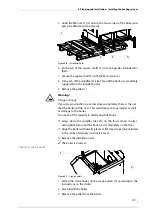
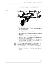
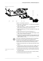
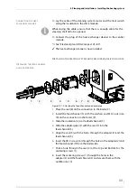
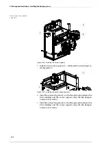
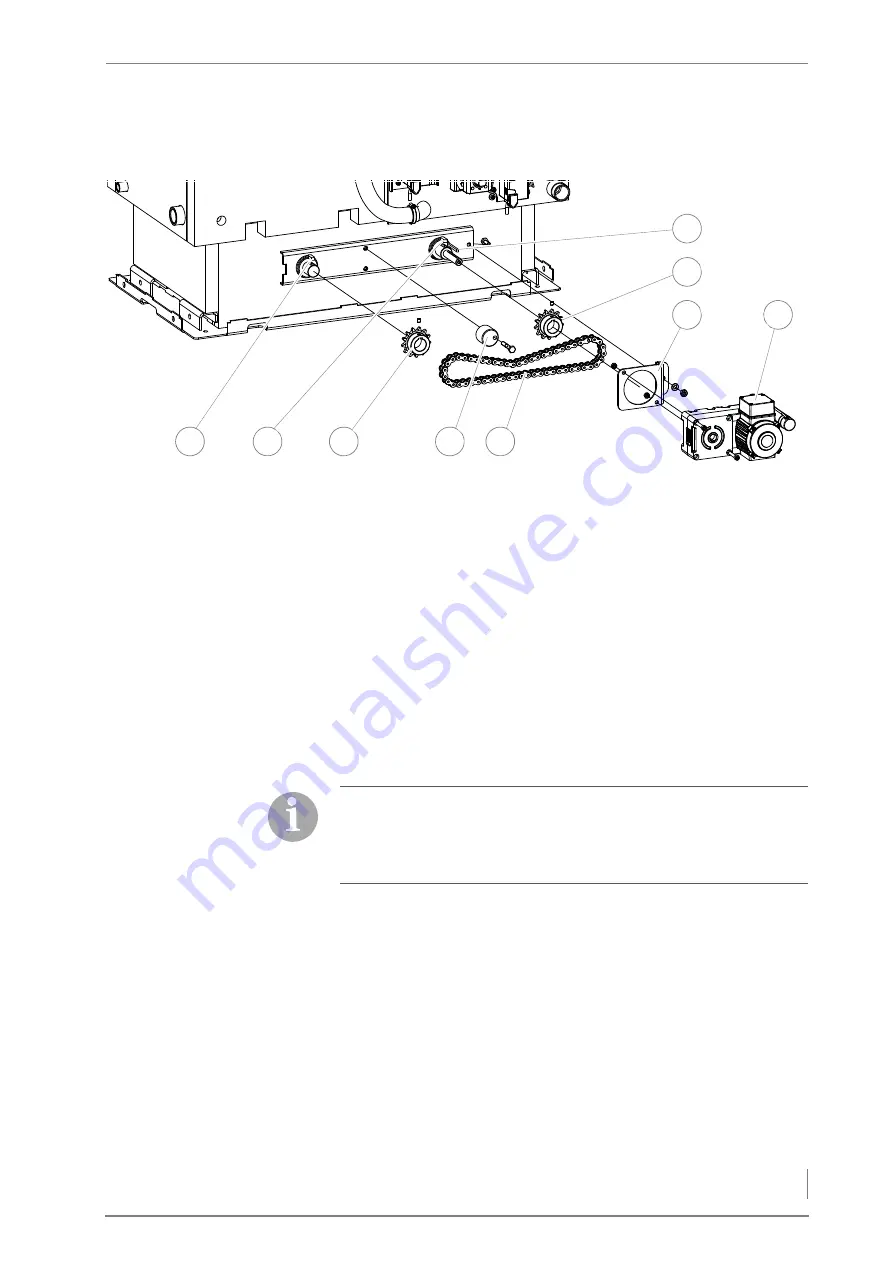
Place the two small feather keys (1 + 2) in the recesses provided for
them on the auger shafts.
15.
Align the sprockets (3 + 7) flush on the auger shafts and fasten
them with the two M8 hexagon socket screws (4 mm).
16.
Place the feather key (6) in the recess provided on the feed side
auger shaft.
17.
Mount the drive chain (5) on the two sprockets (3 + 7).
18.
Fasten the ash removal motor (9) with the M8 hexagon socket
screws (6 mm) on the torque support (8).
19.
Insert the ash removal motor (9) with the torque support (8) on the
feed side auger shaft and fasten the support plate onto the boiler
with the nut (M10, 17 mm).
20.
Mount the chain tensioner (4) on the boiler with the M10 screw
(size 17).
21.
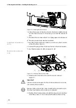
Check the tension of the drive chain in the chain’s middle and use
the chain tensioner if necessary to correct the amount of play.
✎
The drive chain can have about 1 cm of play upward or downward.
C
ONNECTING
THE
ASH
REMOVAL
MOTOR
22.
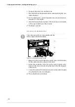
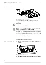
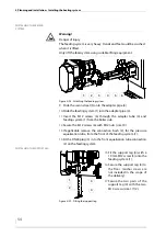
Lay the ash removal motor cable in such a way that it cannot con-
tact the drive chain.
23.
Connect the plug of the ash removal motor to the drive module.
✎
See “Electrical plans HDG Compact 25 - 80”.
Figure 4/21 - Installing the ash removal system
3
2
7
4
5
8
9
6
1
For the version of the boiler with the feeding system on the left side,
the chain tensioner must be fastened in the upper position.
For the version of the boiler with the feeding system on the right
side, the chain tensioner must be fastened in the lower position.
Содержание Compact 25
Страница 1: ...hdg bavaria com HDG Compact 25 35 HDG Compact 45 50 65 HDG Compact 80 Operating manual ...
Страница 2: ......
Страница 6: ...Operation Manual HDG Compact 25 80 Content 6 ...
Страница 107: ......


