background image

Control Pad

The Control Pad has a 15 ft cable with a connector that plugs directly into the Hub as shown on 

page 10. 

Note that there are rubber plugs covering USB port and Ethernet port on the bottom of the Control 

Pad. The ethernet port is available for those that desire a wired connection to their access point, 

rather than using the VS Omni's built-in wifi (see page 21). The USB port is only used for firmware 

upgrades.

Optional Flow Switch

The 15 ft flow switch cable plugs into the flow switch connector shown on page 10.  Ensure that the 

connector catch “snaps” in order to provide a reliable connection.

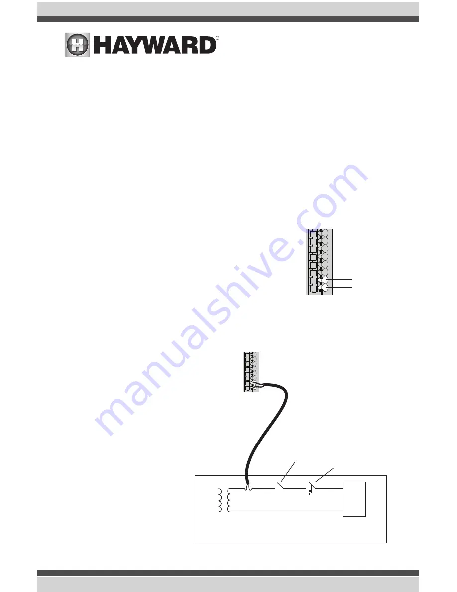
Heater

Ignition/Valve

Heater

Kill Switch

Thermostat

Heaters

The manuals supplied with most heaters also include specific wiring 

instructions for connecting the heater to an external control (usually 

identified as “2-wire” remote control). For millivolt or line voltage 

heaters, contact Hayward Tech support, 908-355-7995.  Refer to 

the information on the following pages for more details on the con-

nection to several popular heaters. Refer to the diagram below for 

the location of heater connections at the Hub.  

Generic Heaters

1.  Wire heater to 115/230V power source per the instructions in the heater manual.  The Hub 

does NOT control the power going to the 

heater.

2.  Wire the Hub dry contact heater output 

per the diagram below.  Many internal 

parts of the heater can get very hot--see 

the heater manufacturer’s recommen-

dations on the minimum temperature 

rating for wires.  If no guidance is given, 

use 105°C rated wire.

3.  Set any ON/OFF switch on the heater to 

ON.

4.  Set the thermostat(s) on the heater to 

the maximum (hottest) setting.

USE ONLY HAYWARD GENUINE REPLACEMENT PARTS

16

Содержание HL23510VSP

Страница 1: ...55 7995 www hayward com VS Omni Pool Automation Control Installation Manual HL32950VVSP HL32900VSP HL26720VSP HL23520VSP HL23510VSP Contents Before you Begin 3 Mounting 7 Plumbing 9 Wiring 10 Startup 22 Configuration 22 092680 RevB USE ONLY HAYWARD GENUINE REPLACEMENT PARTS ...

Страница 2: ...e harmful interference to radio communications However there is no guarantee that interference will not occur in a particular installation If this equipment does cause harmful interference to radio or television reception which can be determined by turning the equipment off and on the user is encouraged to try to correct the interference by one or more of the following measures Reorient or relocat...

Страница 3: ...s 9 Plumbing 9 Electrical Wiring High Voltage 11 Low Voltage 13 System Startup 22 Configuration Pre Programmed Configuration 25 Typical Configuration 25 Advanced Configuration 27 Quick Edit 42 Control Pad MountingTemplate 50 USE ONLY HAYWARD GENUINE REPLACEMENT PARTS 2 USE ONLY HAYWARD GENUINE REPLACEMENT PARTS 2 ...

Страница 4: ...stallation include Wire Wire conduit for incoming power Wire for remote heater control and other low voltage devices Ethernet cable if not using wifi Miscellaneous Valve actuator to automate pool functions see page 9 Flow switch for pump protection flow monitoring Mounting hardware for mounting Hub Control Pad and Smart Relay Cable cord connectors to provide knockout strain relief Wire nut connect...

Страница 5: ...ting etc currently requires Hub to be powered by 230 VAC controls one conventional heater electric heatpump or gas and optional solar heater for single body of water applications only inputs for up to 3 temperature sensors or external input devices built in wireless to connect to the home s router access point ethernet port provided for optional wired connection optional flow switch used to protec...

Страница 6: ...equires a water temperature sensor for heater operation If freeze protection is desired an air temperature sensor is also required For solar heating systems a solar sensor is necessary Even if your instal lation doesn t require the use of temperature sensors installing water and air sensors provides a convenience to the user especially during remote use Flow Switch not included An optional flow sw...

Страница 7: ... VS Omni Hub Control Pad Smart Relay Temperature sensors Valve actuators if applicable 2 Plumbing page 9 General Pool Equipment Flow Switch 3 Electrical Wiring page 10 Hub power Grounding Low voltage wiring Pool Pump Communication Heater Smart Relays Temperature Sensors Flow Switch etc 5 System Startup and Firmware Upgrade page 22 The most common installation technique is described in the included...

Страница 8: ...ounting tabs on the top and bottom of the enclosure requiring a total of 4 fasteners Control Pad The Control Pad comes with a 15 ft cord and plugs into the Hub It should be mounted in a location that is convenient for the user to view and change pool spa settings When considering the mount ing location make sure there is enough clearance above the enclosure so that the flip door will be able to be...

Страница 9: ... Hub with convenient access to the pool equipment that you intend to control with the Smart Relay Three threaded 1 2 NPT knockouts are provided for high voltage power coming into the relay and for power out to the pool equipment A Wiring Whip is included to aid installation The Smart Relay has a manual On Off button that can be used if communication is lost with the Hub Although this button is not...

Страница 10: ... VAC If powering the VS Omni Hub with 115 VAC an actuator can t be used For installation refer to the mounting instructions included with the unit After configuring and first operating the valve note that the internal cams in the actuator may have to be adjusted depending on the way the actuator is mounted on the valve and the desired valve action Plumbing Optional Flow Switch Only applicable if l...

Страница 11: ...ide of the Hub has been provided for all low voltage wiring All low voltage wires should run through this channel to exit the Hub A weather resistant gasket is provided see page 21 to seal this exit Input Power Flow Switch Smart Relays Variable Speed Pump Communication Temperature Sensors External Input Heater Control Pad Valve Actuators Hub must be powered by 230 VAC Wiring Channel Low Voltage Gr...

Страница 12: ...use that connection to provide power to both the Hub and the new variable speed pump VSP Use the included Wiring Whip to aid in this connection The diagram below shows an existing timeclock used to power the old pump This configuration can be easily modified to power the VS Omni and the new VSP Refer to the diagrams below 115 VAC L1 N 230 VAC L1 L2 Connect to Hub and new Variable Speed Pump VSP L1...

Страница 13: ...ry electrical panel to the Hub s ground connection as shown in the previous diagrams Also ground each piece of high voltage equipment that is connected through the Hub or Smart Relay Variable Speed Pump Input Power The VS Omni pump requires a constant 230 VAC 60Hz input power whether from the VS Omni Hub using the Wiring Whip or directly from a service panel switch Refer to the VS Omni Pump manual...

Страница 14: ...s into the box and secure Low Voltage Wiring Note There is a low voltage channel on the right side of the Hub s enclosure labeled on page 10 and shown on page 21 All low voltage wiring that exits the Hub must run through this channel The included foam gasket page 21 should be used to seal the channels s exit after wiring is complete Do not run low voltage wiring through a knockout or with any high...

Страница 15: ... Jandy Actuators have 15 ft cables that are terminated with connectors that plug directly into the Hub as shown on page 10 Temperature Sensors The Hub utilizes 10K ohm thermistor type sensors with 15 ft cable If a longer cable is required con tact the Hayward service dept 908 355 7995 for information on suitable cable types and splices Temperature sensors are wired to the 8 position connector show...

Страница 16: ...n certain conditions exists Connect the external switch as shown below After properly configuring the VS Omni see Configuration Wizard the filter pump and or desired pool equipment will be forced on or off when the external device is activated SPST External Switch Either Normally Open or Normally Closed Push on lever Insert wire here Pool Spa Sensor Air Sensor Optional Solar Sensor or External Inp...

Страница 17: ...nstructions for connecting the heater to an external control usually identified as 2 wire remote control For millivolt or line voltage heaters contact Hayward Tech support 908 355 7995 Refer to the information on the following pages for more details on the con nection to several popular heaters Refer to the diagram below for the location of heater connections at the Hub Generic Heaters 1 Wire heat...

Страница 18: ... diagram on the following page 1 Turn off power to heater 2 Wire Hub to terminals 1 2 see diagram 3 Leave jumper attached to terminals 4 5 4 Move BYPASS dipswitch on heater circuit board to ON position up 5 Turn heater power back on 6 Switch heater to either Pool or Spa it doesn t make any difference which is selected the Hub will take control 7 Heater display should be bO for bypass On 8 Heater w...

Страница 19: ...WN and MODE keys for 3 seconds until the display shows the code bo 6 Be sure to put the heater s control in either POOL or SPA mode 7 The Hub will now control the heater To configure the heater for 2 wire remote thermostat control use the MODE key on the heater keypad to put the control into STANDBY mode Then press and hold both the DOWN and MODE keys for 3 seconds until the display shows the code...

Страница 20: ...s Raypak RP2100 Pool Spa Heater 1 Turn power off to heater 2 Push the mode button to spa mode 3 Set the temperature to the maximum 4 Push the mode button to OFF 5 Lastly plug the prewired connector in the P7 position on the board IMPORTANT The heater will display OFF when it is being remotely controlled by the Hub Some homeowners see the OFF display and thinking this is a mistake change the mode t...

Страница 21: ...emove the jumper for the fireman s switch 4 Wire to the Hub using wire rated for 105 C minimum Transformer 120 V B Y Y W STA RITE Terminal Board Operating Control Fireman s Switch P7 Yellow Black Black Orange Stripe Orange Black Stripe RAYPAK RP2100 USE ONLY HAYWARD GENUINE REPLACEMENT PARTS 20 ...

Страница 22: ...ol Pad and the other to an available LAN port not WAN on the home router Refer to diagram below Final Steps With the wiring complete find the Hub s cover The inside of the cover is made of foam and contains precut removable gaskets shown below that can be used to seal the low voltage exit Remove a gasket and wrap it around the low voltage wiring at the exit of the Hub Work the gasket into the exit...

Страница 23: ...s the first time that the VS Omni has been powered on it will bring you directly to the initial configuration screen shown below Note that the VS Omni Control Pad uses a resistive touch screen that is appropriate for a pool environment It requires a deliberate push when selecting a button At the initial configuration screen touch the en button to select a language the default language is English a...

Страница 24: ...le speed pump one heater gas heat pump and one Smart Relay for a light an air sensor and a water sensor The Pre Programmed Configuration option also comes with the following pre programmed sched ules 1 Filter Pump 8 00 AM to 8 00 PM All Week Medium Speed 2 Light 7 00 PM to 11 00 PM All Week See page 25 for a full Pre Programmed Configuration guide Typical Configuration Use this Configuration Wizar...

Страница 25: ...guide on the subsequent pages until you have completed the Wizard At the end of the Wizard you ll have the opportunity to save your settings or make a change NOTE If additional pool or backyard equipment is added after initial configuration or you d like to make a change to an existing saved configuration re enter the Configuration Wizard and select Edit Current Configuration The initial configura...

Страница 26: ...ton on the bottom of the screen Typical Configuration Wizard Guide As you progress through the Configuration Wizard refer to the following information to help answer questions and make selections Connect to Home Network The first thing you will do in the Configuration Wizard is connect to you home network Refer to the Connect to Home Network section on page 24 for more information on this part of ...

Страница 27: ...uld like to con figure a pump driven accessory NOTE this option only appears if more than one variable speed pump is discovered If Yes is selected Select the type of pump driven accessory water feature cleaner accessory If Water Feature Cleaner or Accessory is selected Which Hayward Unique Address Select the HUA of the water feature clean er or accessory s variable speed pump NOTE this option only...

Страница 28: ...be displayed in Celsius and chemistry readings will be in g L Select Desired Units of Measure Speed in or Speed in RPM If Speed in is selected then pump speeds will be displayed in If Speed in RPM is selected then pump speeds will be displayed in RPM MSP ID The VS Omni MSP ID number will be displayed This unique number is used to identify your VS Omni when setting up a web account A web account is...

Страница 29: ...x es and you can advance to the next screen to continue the pump configuration Filter Pump Off for Valve Change When Yes is selected the pump will shut off for 35 seconds whenever a valve changes position Flow Monitoring Enabled Requires use of a Hayward flow switch This feature will help protect the filter pump from damage due to no flow When Yes is selected the VS Omni will monitor the state of ...

Страница 30: ...be used when setting schedules for your pump Filter Pump Off for Valve Change When Yes is selected the pump will shut off for 35 seconds whenever the valve s change position Flow Monitoring Enabled Requires use of a Hayward flow switch This feature will help protect the filter pump from damage due to no flow When Yes is selected the VS Omni will monitor the state of water flow when the filter pump...

Страница 31: ...ature This is the maximum allowed setting for the heater regardless of its default range There may be circumstances where you will want to limit the high temperature of your heater to a temperature that is lower than the factory high setting Select and Configure a Heater At this screen you can add delete and configure your heater s Select the desired heater then touch the Advance button When finis...

Страница 32: ... demand within this time frame the next heater will not be used Note that a time interval setting of 0 will eliminate priority and always run both heaters at the same time Minimum Allowed Air Temperature for Heater If the air temperature falls below this setting the heater will be prevented from running regardless of conditions This feature is especially useful for heat pumps which become less eff...

Страница 33: ...nd the next heater will start selection 2 Heater Priority Duration Set the amount of time that you will allow the priority heater 1 to heat before allowing the next heater to start If the priority heater meets the demand within this time frame the next heater will not be used Note that a time interval setting of 0 will eliminate priority and always run both heaters at the same time Minimum Operati...

Страница 34: ...value is shown selecting the box will bring you to a table show ing all detected devices Select the proper HUA from the table and touch the Done button The address should now be shown in the box and you can advance to the next screen to continue the VSP configuration Pump Capacity Set the minimum and maximum RPM of the pump Refer to your pump manual for more information Permitted User Setting The ...

Страница 35: ...s active Select the desired pump speed NOTE this option only appears if the pump is a two speed pump or a variable speed pump How Many Water Features Enter the number of water features that you have connected to the VS Omni If 1 or more is selected Type of Water Feature Touch the box and select the type of water feature used Choic es are Water Feature Water Slide Waterfall and Fountain Name of Wat...

Страница 36: ... is the Valve s Wired Selecting the box will bring you to a table show ing all detected low voltage relays Select the relay s that is wired to the water feature valve s then advance The valve s should now be shown in the box Advance to the next screen to continue Would You Like to Enable Priming Select whether you want the pump to prime when turned on This will turn the pump on at high speed for 3...

Страница 37: ...t this screen you can add delete and configure your accessories Select the desired accessory then touch the Advance button When finished configuring accessories you ll be returned to this same screen Touch the Done button and advance to the next section of configuration Refer to the following information when configuring accessories Type of Accessory Touch the box and select the type of accessory ...

Страница 38: ...e box will bring you to a table show ing all detected low voltage relays Select the relay s that is wired to the ac cessory valve s then advance The valve s should now be shown in the box Advance to the next screen to continue accessory configuration Would You Like to Enable Priming Select whether you want the pump to prime when turned on This will turn the pump on at high speed for 3 minutes to e...

Страница 39: ...vance to the next screen to continue configuration Select and Configure Sensors At this screen you can add delete and configure your sensors Select the desired sensor then touch the Advance button When finished configuring sensors you ll be returned to this same screen Touch the Done button and advance to the next section of configu ration Refer to the following information when configuring sensor...

Страница 40: ...e shown in the box and you can advance to the next screen to continue the accessory configuration NOTE Do not use the VS Omni to control fire pits or any other fire related equip ment Would You Like to Add an Interlock An interlock will allow the VS Omni to turn on or to turn off a piece of pool equipment slave based on the state of other pool equipment master An example of this is would be the de...

Страница 41: ... Equipment B located below the interlock statement to choose the equipment that you would like to interlock Pressing either button will bring you to another screen with all of the possible equipment that can be interlocked Choose the desired equipment and then press save to lock in those values After saving the equipment the interlock statement will change to include your selected equipment Verify...

Страница 42: ...nterlock If Equipment to External Input is selected requires that you have an external input configured Select Interlock Statement Use the right and left arrows to choose the de sired behavior of the interlock The behavior for each interlock statement is described below If the External Input is closed the Equipment can not be on The Equip ment can only turn on if the External Input is open If the ...

Страница 43: ...pment can only be turned on if the Temp Sen sor reads less than the selected Temperature set point If the Equipment is run ning and then the Temp Sensor reaches the selected Temperature set point the Equipment will turn off The Equipment can be controlled independently as long as the Temp Sensor reads less than the selected Temperature set point If the Temp Sensor reads less than Temperature degre...

Страница 44: ...with Configuration Now that all equipment has been configured select the following Customizing Add Components use this selection to go back into Configuration and make changes Save and Restart this selection will save your configuration settings and restart the VS Omni Quick Edit Guide If additional pool or backyard equipment is added after initial configuration or you d like to make a change to a...

Страница 45: ...ain each configuration pathway Begin Using Quick Edit From the Quick Main Menu Screen select one of the following buttons and follow the directions on the next page to configure your equipment Pool or the name given to the body of water Backyard Sensors Interlocks Add Interlock System Options If Pool body of water name is selected Select the Equipment that you would like to configure The options a...

Страница 46: ... Pressing Add a Heater from this screen will take you through the full configuration for adding a new heater These steps are described in the Advanced Configuration Guide section of this manual General Heater Options Pressing this button will take you to a screen will the following general options for heater operation Extend If Enabled the filter extend logic keeps the filter pump running beyond t...

Страница 47: ... the solar sensor This option is only available if the heater is configured as a Solar heater Delete a Heater From this screen if you wish to delete a heater that is currently configured select the Delete button can on the right of the name of the heater that you wish to delete If Cleaners is selected Add Cleaner Pressing Add Cleaner from this screen will take you through the full configuration fo...

Страница 48: ...feature These steps are de scribed in the Advanced Configuration Guide section of this manual Select a Water Feature Once you select a water feature all of the options for that water feature will appear on the next screen These options are as follows Name Create a custom name if desired Type Change the type of water feature that is configured Waterfall Waterslide etc Pump Configure the water featu...

Страница 49: ...f the lights configured UCL CL4 0 or CL 2 5 Delete Group of Lights From this screen if you wish to delete a group of lights that is currently configured select the Delete button on the right of the name of the lights group that you wish to delete If Accessories is selected Add Accessory Pressing Add Accessory from this screen will take you through the full configuration for adding a new accessory ...

Страница 50: ... Configuration Guide section of this manual Select Group of Lights Once you select a group of ColorLogic Standalone Lights all of the options for those lights will appear on the next screen These options are as follows Name Create a custom name if desired Type Select the type of lights configured UCL CL 4 0 or CL 2 5 Relay Select the relay s that is wired to the group of lights Set Mode Set the mo...

Страница 51: ...r that you wish to delete If Interlocks is selected Add Interlock Pressing Add Interlock from this screen will take you through the full con figuration for adding a new interlock These steps are described in the Configuration Guide portion of this manual Select an Interlock Selecting an interlock from this screen will allow you to view that in terlock s configuration However you cannot edit a pre ...

Страница 52: ...51 USE ONLY HAYWARD GENUINE REPLACEMENT PARTS ...

Страница 53: ...USE ONLY HAYWARD GENUINE REPLACEMENT PARTS 52 ...

Страница 54: ...53 USE ONLY HAYWARD GENUINE REPLACEMENT PARTS ...

Страница 55: ...Control Pad Mounting Template USE ONLY HAYWARD GENUINE REPLACEMENT PARTS 54 ...

Страница 56: ... and Hub is a trademark of Hayward Industries Inc 2017 Hayward Industries Inc All other trademarks not owned by Hayward are the property of their respective owners Hayward is not in any way affiliated with or endorsed by those third parties USE ONLY HAYWARD GENUINE REPLACEMENT PARTS USE ONLY HAYWARD GENUINE REPLACEMENT PARTS ...

Отзывы: