Helicopter mechanics
with model turbine engine
22
5. Assembling the tail rotor head
(bag UM-11C)
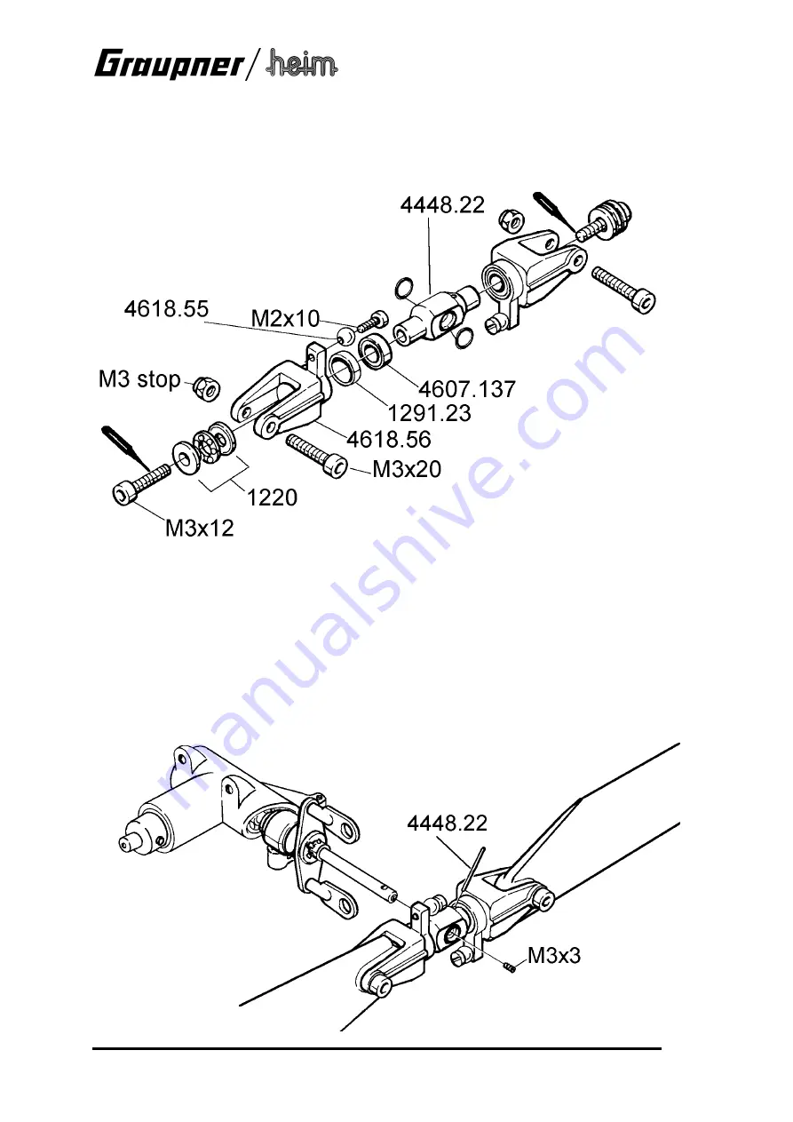
Assemble the tail rotor head as shown in the drawing, not forgetting to grease all the bearings.
Apply some bearing lock fluid to the Screws M3x12 and tighten them only so far that the
bladeholders still rotate smoothly.
Take care not to allow the bearing lock fluid to get into the bearings!
Press the two O-rings into the hub 4448.22 so that they are located fully in the recesses. Oil the
O-rings, and slide the tail rotor head onto the tail rotor shaft. The cross-hole in the shaft must
line up with the hole in the hub; the pin 4448.22 can then be pushed through to secure the parts.
The pin in turn is retained by the M3 x 3 grubscrew.
Note the orientation of the hub (see illustration).
Fit the tail rotor blades in the blade holders using the M3 x 20 screws. Tighten them to the point
where they can swivel quite easily, so that they find their optimum position automatically when
the system is operating.
Note the orientation of the tail rotor blades: when viewed from the left-hand side, the tail rotor
spins clockwise („bottom blade forward“), and the blade pitch arms on the blade holders must
be in front of the blades.
Содержание JetCat 6810
Страница 31: ...31 Bedienungsanleitung ...
Страница 101: ...31 Operating Instructions Graupner Jetcat Modell Helicopter Turbine PHT 3 ...
Страница 107: ...37 Wiring diagram fuel pump and starter glowplug Connections overwiew of the turbine s operating components ...
Страница 171: ...31 Instructions d utilisation ...
Страница 177: ...37 Schéma de connexion Pompe à carburant et Starter Bougie Connexions des éléments de commande Généralité ...


