background image

om 5184516-100 Rev. 5

5-35

Add Protocol

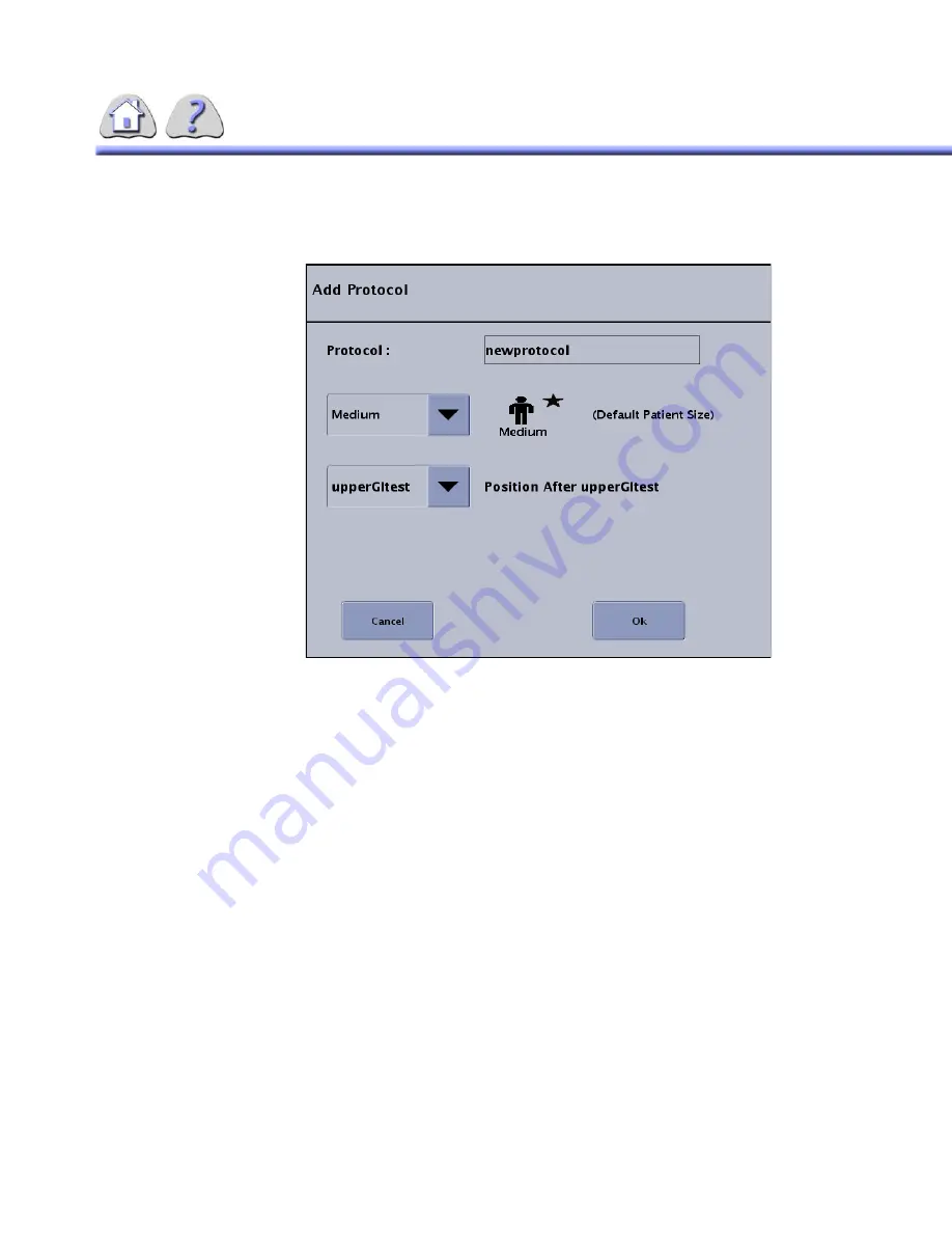
When Add Protocol is selected, a pop–up window appears as shown below:

ILLUSTRATION 5-34

ADD PROTOCOL

The user is able to name the new Protocol. Select the box in order to enter the
Protocol name. The length of the name is limited to 12 characters.

Select Patient Size for Patient Default size. S, M, L and PED.

The user is able to place where the protocol should be positioned in the category
list.

“Position (After)” is included above the location drop down to clarify what the field
is for.

The star and the text “Default Patient Size” is included after the patient size icon to
verify what the selected default Patient Size is.

The user is able to set the default Patient Size. This Patient Size is used as the
default for all Tube 2 Protocol Steps. The benefit of having this parameter at the
Protocol level is that if the Patient Size has to be changed (say from Medium to
Ped [pediatric]), it only has to be changed in one place and not in each Protocol
Step. When the pop–up appears, the default factory Patient Size is set to Medium.

The user is able to place the new Protocol in any position. When the user is add-
ing the 1st Protocol, the selection is read “First” and the control is grayed out /
inactive. All categories are listed in creation order or user-defined order in the
drop down menu.

The “OK” button will be grayed out / inactive until valid entries have been made.

When the user selects OK, the pop–up is closed and the new protocol is added to
the right of the main screen and selected.

FOR 

TRAINING 

PURPOSES 

ONLY! 

NOTE: 

Once 

downloaded, 

this 

document 

is 

UNCONTROLLED, 

and 

therefore 

may 

not 

be 

the 

latest 

revision. 

Always 

confirm 

revision 

status 

against 

validated 

source 

(ie 

CDL).

Содержание Precision 500D

Страница 1: ...ion 500D R F System Operator Manual Copyright 2007 By General Electric Co FOR TRAINING PURPOSES ONLY NOTE Once downloaded this document is UNCONTROLLED and therefore may not be the latest revision Always confirm revision status against a validated source ie CDL ...

Страница 2: ...5184516 100 Rev 5 FOR TRAINING PURPOSES ONLY NOTE Once downloaded this document is UNCONTROLLED and therefore may not be the latest revision Always confirm revision status against a validated source ie CDL ...

Страница 3: ... 4 October 3 2007 Updated Table 7 1 Items 6 and 8 to identify X ray control unit depending upon date of manufacture Added model numbers to Table 7 1 row 1 Overhead tube Collimator and row 4 Precision 500D R F Table Collimator Added note about radiopacity after table 7 12 Added ifnormation on collimator lamp replacement for model 5234954 in Chapter 8 Added mR mAs calibration and maintanence frequen...

Страница 4: ...THIS PAGE INTENTIONALLY LEFT BLANK FOR TRAINING PURPOSES ONLY NOTE Once downloaded this document is UNCONTROLLED and therefore may not be the latest revision Always confirm revision status against a validated source ie CDL ...

Страница 5: ...ials and Methods 2 6 4 3 Results 2 7 SECTION 5 SAFETY 2 16 5 1 General Precautions 2 16 5 2 Electrical Safety 2 20 5 3 Patient Positioning and Control 2 21 5 4 Table Angulation 2 21 5 5 Unsafe Table Region 2 21 5 6 Patient Grasp Handles 2 22 5 7 Safety Harness 2 22 5 8 Reciprocating Bucky 2 22 5 8 1 Travel and Counterbalancing 2 23 5 9 Bucky Grids 2 23 5 9 1 Oscillating Grid 2 23 5 9 2 Single High...

Страница 6: ...ON 4 OPTIONS 3 2 4 1 DICOM 3 0 Interface Option 3 2 4 2 Bar Code Scanner Option 3 2 4 3 International Keyboard Option 3 2 SECTION 5 POWER UP POWER DOWN 3 3 SECTION 6 OVERVIEW 3 3 6 1 Keyboard 3 5 6 2 Mouse 3 5 6 3 Radiology Control Interface Module RCIM 3 5 SECTION 7 X RAY TUBE SELECTION 3 7 7 1 X ray tube 1 3 7 7 2 X ray tube 2 3 8 CHAPTER 4 GETTING STARTED SECTION 1 INTRODUCTION 4 1 SECTION 2 ST...

Страница 7: ...o Local CD RW OPTION 5 22 2 10 Emergency Recovery 5 24 SECTION 3 EDIT PROTOCOLS 5 25 3 1 Protocol Editor 5 25 3 2 Protocols 5 26 3 2 1 Parameters for Tube 1 Fluoro Protocol Step 5 27 3 2 2 Parameters for Tube 2 RAD Protocol Step 5 28 3 2 3 Protocol Categories 5 29 3 2 4 Protocols 5 31 3 2 5 Protocol Steps 5 38 3 2 6 Retrieve 5 52 3 2 7 Back Up 5 53 3 2 8 System Configuration Changes 5 53 3 3 User ...

Страница 8: ...Tab 5 58 3 6 System Shutdown 5 59 SECTION 4 IN ROOM REMOTE KEYPAD OPTION 5 60 4 1 IR Remote Keypad Commands 5 61 CHAPTER 6 DIGITAL IMAGING SYSTEM SECTION 1 MENU DISPLAYS 6 1 1 1 Digital Image Main Screen 6 1 1 2 Disk Space Indicators 6 2 SECTION 2 EDIT SERIES TITLE 6 3 SECTION 3 PATEINT LIST SCREEN 6 5 SECTION 4 AUTO SEND TO REFERENCE IMAGE MONITOR WITH REFERENCE MONITOR INSTALLED 6 7 SECTION 5 SE...

Страница 9: ...MATS 6 21 SECTION 16 DELETE IMAGE 6 22 16 1 Annotations Pointers 6 23 SECTION 17 PRINTING AN IMAGE 6 25 SECTION 18 STENOSIS MEASURMENT FEATURES AND STEPS 6 25 18 1 Calibration 6 26 18 2 Size 6 29 18 3 Reference 6 29 18 4 Occlusion 6 30 18 5 Manual Boundary 6 31 18 6 Auto Boundary 6 33 18 7 Running Length 6 33 18 8 Show Data 6 34 SECTION 19 DICOM WORKLIST REQUIRES DICOM OPTION 6 35 CHAPTER 7 TABLE ...

Страница 10: ...le Electrical Requirements 7 33 3 2 Precision 500D Tables Tubes and Collimators 7 34 3 2 1 X Ray Tube Specification 7 34 SECTION 4 OPERATION 7 35 4 1 Parking Docking the Imaging Device Carriage 7 35 4 2 Fluoro Exposures 7 37 4 2 1 Footswitch 7 37 4 3 Taking Digital Exposures 7 38 4 3 1 Using the Prep Record Bar 7 38 4 3 2 Using the Integrated Fluoro Expose Switch 7 38 4 4 Equipment Positioning for...

Страница 11: ...N 2 PARTS OF THE EQUIPMENT 9 2 2 1 Column Assembly 9 2 2 2 Bucky Assembly 9 3 2 3 Front Panel 9 3 2 4 Vertical Lock Handle 9 3 SECTION 3 APPLICATIONS OF SG80 120 9 3 SECTION 4 OPERATION 9 3 4 1 Vertical Positioning 9 3 4 2 Cassette Loading 9 4 4 3 Cassette Removal 9 6 4 4 AEC Detector Areas 9 6 4 5 Alignment 9 6 4 6 Frontal Panel 9 7 4 7 SG120 Specific Funtionalities 9 7 4 7 1 Bucky Rotation 9 7 4...

Страница 12: ...Manual Cassette Tray 10 9 3 11 AEC Detector Areas 10 9 3 12 Alignment 10 9 3 13 Manual Cassette Tray 10 10 3 14 Alignment for Automatic Collimation 10 10 SECTION 4 SPECIFICATIONS 10 11 4 1 General Dimensions Weight 10 11 4 2 Column Assembly 10 12 4 3 Front Panel 10 12 4 4 Power Requirements 10 12 4 5 Bucky 10 13 4 6 Accessories Options 10 13 CHAPTER 11 JEDI GENERATOR SECTION 1 INTRODUCTION 11 1 SE...

Страница 13: ...1 SECTION 2 FEATURES A 1 2 1 Tube Housing A 2 2 2 Tube Insert A 3 2 3 Thermal Ratings A 3 2 4 Radiographic Ratings A 4 2 5 Fluoroscopic Ratings A 4 SECTION 3 WEIGHTS APPROX A 4 SECTION 4 RELATED PUBLICATIONS A 4 SECTION 5 WARRANTY A 5 SECTION 6 USER SERVICE AND MAINTENANCE A 5 SECTION 7 LISTINGS A 5 SECTION 8 RADIOGRAPHIC TUBE RATINGS A 8 8 1 Warm Up Procedure A 8 8 2 12 5 218 mRad 3ø Low Speed 50...

Страница 14: ...10 3 3Ø KILOWATT RATINGS 12 5 218 mRad A 22 CHAPTER B PLANNED MAINTENANCE SECTION 1 TABLE PM B 1 1 1 Periodic Maintenance B 1 1 2 Qualified Service B 1 1 3 User Service and Maintenance B 1 SECTION 2 IMAGE QUALITY TESTING B 2 2 1 How to perform the Quality Assurance Process B 4 SECTION 3 GENERAL B 10 3 1 Periodic Maintenance Schedule B 11 SECTION 4 SERVICE B 11 4 1 User Cleaning and Disinfecting B ...

Страница 15: ... D 4 2 6 How mode should be used D 4 SECTION 3 DIGITAL SUBTRACTION ANGIOGRAPHY DSA MODE D 4 3 1 Description D 4 3 2 System Controlled Technique Factors D 4 3 3 How to engage disengage D 4 3 4 How to recognize when this mode is selected D 5 3 5 Example of specific clinical procedures D 6 3 6 How mode should be used D 6 SECTION 4 RADIOGRAPHIC MODE D 6 4 1 Description D 6 4 2 System Controlled Techni...

Страница 16: ...5184516 100 Rev 5 FOR TRAINING PURPOSES ONLY NOTE Once downloaded this document is UNCONTROLLED and therefore may not be the latest revision Always confirm revision status against a validated source ie CDL ...

Страница 17: ...riety of education methods including clinical working experience hospital based pro grams and as part of many college and university Radiological Technology pro grams SECTION 3 SAFETY NOTICES The following are used to emphasize certain safety instructions This guide used the international symbol along with the danger warning or caution message This section also describes the purpose of a Note DANG...

Страница 18: ... This symbol indicates that the waste of electrical and electronic equipment must not be disposed as unsorted municipal waste and must be collected sepa rately Please contact an authorized representative of the manufacturer for information concerning the decommissioning of your equipment FOR TRAINING PURPOSES ONLY NOTE Once downloaded this document is UNCONTROLLED and therefore may not be the late...

Страница 19: ... number and send them to GENERAL ELECTRIC COMPANY MEDICAL SYSTEMS MANAGER INFORMATION INTEGRATION AMERICAS W 622 P O BOX 414 MILWAUKEE WI 53201 0414 INDICATIONS FOR USE The Precision 500D R F X ray System is indicated for use in generating radio graphic and fluoroscopic images of human anatomy in all general purpose X ray diagnostic procedures SECTION 2 WHAT DO I NEED TO KNOW ABOUT This section pr...

Страница 20: ...l use the equipment before you attempt to place this equip ment in operation The General Electric Company Medical Systems Group will be glad to assist and cooperate in placing this equipment in use Although this apparatus incorporates a high degree of protection against x radia tion other than the useful beam no practical design of equipment can provide complete protection Nor can any practical de...

Страница 21: ... and the accompanying electrical installations are highly sophisticated and special engineering competence is required In performing all electrical work on these products GE will use its own specially trained field engineers All of GE s electrical work on these products will comply with the requirements of the applicable electrical codes The purchaser of GE equipment shall only utilize qualified p...

Страница 22: ...en the equipment and the affected device Power the equipment from a source different from that of the affected device Consult the point of purchase or service representative for further suggestions The manufacturer is not responsible for any interference caused either by the use of interconnect cables other than those recommended or by unauthorized changes or modifications to this equipment Unauth...

Страница 23: ...certain Electro Static Discharge ESD and Electrical Fast Transient EFT conditions noise may appear on video monitors and recorders This noise should disappear spontaneously when the stimulus is removed If the problem persists call Service Under certain conditions ESD may cause temporary anomalies to be present on the image monitors and the VCR This is a temporary degradation during the ESD event a...

Страница 24: ... a 25 cm cube of polymethyl methacrylate PMMA centered on the tabletop The entrance surface of the image intensifier was set at a distance of 30 cm above the tabletop The nominal field size was 22 cm The x ray tube voltage was at the maximum fluoroscopic value of 120 kVp and the x ray tube current was 4 6 mA This resulted in an entrance area kerma product of 900 RVcm min This was used to normalize...

Страница 25: ... practical to the x ray unit In areas close to the x ray unit where the stray radiation field changed rapidly the spacing between measurements was reduced to 25 cm to further improve the accuracy of the isokerma maps 4 3Results Measured values of air kerma were normalized to 1 GyVcm as specified in the IEC standard and used to construct isokerma contours at values of 16 8 4 2 1 0 5 0 25 0 12 0 06 ...

Страница 26: ...84516 100 Rev 5 2 8 FOR TRAINING PURPOSES ONLY NOTE Once downloaded this document is UNCONTROLLED and therefore may not be the latest revision Always confirm revision status against a validated source ie CDL ...

Страница 27: ...84516 100 Rev 5 2 9 FOR TRAINING PURPOSES ONLY NOTE Once downloaded this document is UNCONTROLLED and therefore may not be the latest revision Always confirm revision status against a validated source ie CDL ...

Страница 28: ...4516 100 Rev 5 2 10 FOR TRAINING PURPOSES ONLY NOTE Once downloaded this document is UNCONTROLLED and therefore may not be the latest revision Always confirm revision status against a validated source ie CDL ...

Страница 29: ...4516 100 Rev 5 2 11 FOR TRAINING PURPOSES ONLY NOTE Once downloaded this document is UNCONTROLLED and therefore may not be the latest revision Always confirm revision status against a validated source ie CDL ...

Страница 30: ...4516 100 Rev 5 2 12 FOR TRAINING PURPOSES ONLY NOTE Once downloaded this document is UNCONTROLLED and therefore may not be the latest revision Always confirm revision status against a validated source ie CDL ...

Страница 31: ...4516 100 Rev 5 2 13 FOR TRAINING PURPOSES ONLY NOTE Once downloaded this document is UNCONTROLLED and therefore may not be the latest revision Always confirm revision status against a validated source ie CDL ...

Страница 32: ...4516 100 Rev 5 2 14 FOR TRAINING PURPOSES ONLY NOTE Once downloaded this document is UNCONTROLLED and therefore may not be the latest revision Always confirm revision status against a validated source ie CDL ...

Страница 33: ...4516 100 Rev 5 2 15 FOR TRAINING PURPOSES ONLY NOTE Once downloaded this document is UNCONTROLLED and therefore may not be the latest revision Always confirm revision status against a validated source ie CDL ...

Страница 34: ...operating procedures are being used THIS X RAY UNIT MAY BE DANGEROUS TO PATIENT AND OPERATOR UNLESS SAFE EXPOSURE FACTORS OPERATING INSTRUCTIONS AND MAINTENANCE SCHEDULES ARE OBSERVED TO BE USED BY AUTHORIZED PERSONNEL ONLY ELECTRIC SHOCK HAZARD DO NOT REMOVE COVERS OR PANELS CONSOLE AND CABINETS CONTAIN HIGH VOLTAGE CIRCUITS FOR GENERATING AND CONTROLLING X RAYS PREVENT POSSIBLE ELECTRIC SHOCK BY...

Страница 35: ... func tions during an exam Always be alert to safety when you operate this equipment You must be familiar enough with the equipment to recognize any malfunctions that can be a hazard If a malfunction occurs or a safety problem is known to exist do not use this equipment until qualified personnel correct the problem ESTABLISH PROCEDURES FOR HANDLING THE PATIENT IN CASE OF THE LOSS OF FLUOROSCOPIC I...

Страница 36: ... EDGE OR END OF THE TABLE SERIOUS INJURY MAY RESULT USE THE PATIENT GRASP HANDLES THE SAFETY HARNESS THE SHOULDER REST THE FOOT REST AND OTHER SAFETY MEASURES AS APPROPRIATE TO PREVENT ACCIDENTS IT IS THE RESPONSIBILITY OF THE OPERATOR TO PROVIDE MEANS FOR AUDIO AND VISUAL COMMUNICATION WITH THE PATIENT FROM THE CONTROL ROOM PATIENT INJURY MAY OCCUR ALWAYS ASSIST THE PATIENT ON OR OFF THE TABLE AT...

Страница 37: ...of a 136 kg 300 lbs patient Excessive loading could damage the tabletop and or cause the patient to fall Accessories should be properly attached to the table and positioned so as not to interfere with system motions Avoid unnecessary exposure to radiation Stay behind the lead glass radi ation shield or lead screen When in unshielded areas wear protective apparel such as goggles lead aprons and glo...

Страница 38: ...formance requires the use of service personnel specially trained on x ray apparatus GE Medical Systems is responsible for the effects on safety reliability and performance only if the following conditions are met The electrical wiring of the relevant rooms complies with all national and local codes as well as the Regulations for the Electrical Equipment of Buildings published by the Institution of...

Страница 39: ...t of an unsafe region 1 Center the table top If full table motion is not available then 2 Move the table into the horizontal position If full table motion is still not available 3 Remove patient from table safely and call GE Service PATIENT INJURY MAY OCCUR ALWAYS ASSIST THE PATIENT ON OR OFF THE TABLE AT THE BEGINNING OR END OF AN EXAM WHEN MOVING THE TABLE TOP BUCKY OR OTHER ELEMENTS BE SURE THE...

Страница 40: ...support the weight of a 300 lb 136 kg patient 5 8Reciprocating Bucky Injury could occur from unintended motion Remove patient from the table and call Service PATIENT MAY FALL OR ROLL OFF TABLE USE SAFETY HARNESS WHENEVER POSSIBLE NEVER LEAVE THE PATIENT UNATTENDED THE BUCKY ASSEMBLY IS UNBALANCED WHENEVER THE CASSETTE TRAY IS REMOVED WHILE THE TABLE IS IN THE VERTICAL OR TRENDELENBURG POSITION TO ...

Страница 41: ...cky grid oscillates during the X ray exposure X ray exposures are pre vented until the grid is in motion 5 9 2 Single High Line Rate Grid A 12 1 or 8 1 high line rate stationary grid is available The single high line rate grid does not oscillate 5 9 3 Bucky Grid Alignment Centering Density cutoff at the edges of the film and the appearance of grid patterns indicate inaccurate lateral alignment Lat...

Страница 42: ... the safety latches with the thumbs and spread the handles 2 Place the foot rest on the top adjacent to a set of slots and release the han dles 3 Slide the foot rest until both handles snap into place INJURY COULD OCCUR IF PATIENT STEP IS NOT FULLY OUT VERIFY PATIENT STEP IS FULLY ENGAGED AND ASSIST THE PATIENT ON AND OFF THE TABLE TO PREVENT IMPROPER ATTACHMENT AND POTENTIAL INJURY TO PATIENT USE...

Страница 43: ...qualified technician ILLUSTRATION 2 3 FOOT REST 5 12Shoulder Rest The shoulder rest ILLUSTRATION 2 4 is engaged on the table top in the same manner as the foot rest The plunger locks permit adjustment of the pad position in 1 2 increments ILLUSTRATION 2 4 SHOULDER REST FOR TRAINING PURPOSES ONLY NOTE Once downloaded this document is UNCONTROLLED and therefore may not be the latest revision Always ...

Страница 44: ... handle and disengaging the band ILLUSTRATION 2 5 COMPRESSION DEVICE 5 14Myelographic Operation For myelographic procedures the Horizontal Stop selection located on the table control panel should be off This inhibits accidental motion of the cone during the procedure To set the myelographic stop 1 Press the button move stop up or down and release it 2 Then move the spot film device against it to m...

Страница 45: ...on 1 Move the apron handle to position the lead apron Position the handle between the two lines for horizontal work Outside the rear line it will slide as the table is angulated in position for vertical work Refer to ILLUSTRATION 2 7 2 To remove the Lead Apron a Pull out release button and pull handle handle down b Slide apron out of track towards rear of spot film device Ensure that spot film dev...

Страница 46: ...tantly cut power to the table To restore power Verify table is safe to angulate or move Push turn and release the Emergency Stop Button THE LEAD APRON PROTECTS THE OPERATOR FROM ANY SCATTER RADIATION IT SHOULD REMAIN ATTACHED TO THE IMAGING DEVICE AT ALL TIMES THIS LEAD APRON MUST BE INSTALLED IN ORDER TO MEET THE RADIATION PROTECTION REQUIREMENTS OF IEC 601 1 3 THIS LEAD APRON IS PART OF THE PRIM...

Страница 47: ... OPERATION OF THIS BUTTON BEFORE EACH USE THE PATIENT MUST NOT BE ADMITTED UNLESS THIS SAFETY FEATURE IS OPERATIONAL FOR TRAINING PURPOSES ONLY NOTE Once downloaded this document is UNCONTROLLED and therefore may not be the latest revision Always confirm revision status against a validated source ie CDL ...

Страница 48: ...r end These cables connect accessory equipment to the table base receptacles 5 19 3 Instructions Check all the table motions required for the procedure with all ground cords equipment and personnel in place BEFORE bringing a patient into an examination room To connect a locking pin grounding cable to a ground receptacle press the plug into the receptacle and rotate the plug slightly clockwise The ...

Страница 49: ... be performed daily prior to patient data acquisition This can be done by acquiring images using a phantom retrieving them and then deleting the file per the operating instructions in this manual The system should not be operated such that a patient could come in contact with any part of the system FEDERAL LAW RESTRICTS THIS DEVICE TO SALE BY OR ON THE ORDER OF A PHYSICIAN THIS INSTRUMENT MUST BE ...

Страница 50: ...t to remove any panels or replace any parts Refer all servicing to qualified service personnel only Dosimeters must be worn by all personnel during all phases of installation operation and maintenance of the system and the equipment to which it is interfaced Do not attempt to alter any system software Doing so could disrupt the functioning of the instrument and result in loss of images Use of any ...

Страница 51: ...e present on the image monitors This is a temporary degradation during the transient event and does not cause any system issues FOR TRAINING PURPOSES ONLY NOTE Once downloaded this document is UNCONTROLLED and therefore may not be the latest revision Always confirm revision status against a validated source ie CDL ...

Страница 52: ...34 THIS PAGE INTENTIONALLY LEFT BLANK FOR TRAINING PURPOSES ONLY NOTE Once downloaded this document is UNCONTROLLED and therefore may not be the latest revision Always confirm revision status against a validated source ie CDL ...

Страница 53: ...lar area of interest and choose the optimum visualization of a given pathology The system provides the ability to print images to traditional film output devices You can print images using whatever formats are supported by your multi format camera or laser film recorder The system also allows you to archive images using a variety of devices including DICOM 3 0 compatible network devices and MOD Re...

Страница 54: ... data Auto Transfer to DICOM device Annotations included in Image Transfer Patient Data included with Image Transfer and DICOM WorkList Query Import Patient files including just patient data or patient data with images can be imported to the system using DICOM transfer or DICOM WorkList queries 4 2Bar Code Scanner Option The digital system can now interface with a Bar code scanner to allow for mor...

Страница 55: ...he system The Power On button is located on the RCIM it is the button next to the Emergency Stop See Radiology Control Interface Module RCIM on page 5 POWER DOWN 1 End all sessions and log out using the Shut Down command found in Utilities Tab The system will automatically power down SECTION 6 OVERVIEW The physical operation of the original x ray generator control devices will remain the same as t...

Страница 56: ...few feature controls see ILLUSTRATION 3 1 Sometimes menus are shown over the image portion of the screen The sys tem operation is designed such that these menus do not usually interfere with the normal image viewing ILLUSTRATION 3 1I ACQUIRE GENERAL SCREEN FOR TRAINING PURPOSES ONLY NOTE Once downloaded this document is UNCONTROLLED and therefore may not be the latest revision Always confirm revis...

Страница 57: ...ft mouse button 6 3Radiology Control Interface Module RCIM The Radiology Console Interface Module RCIM ILLUSTRATION 3 2 controls the power and reset functions for the system The RCIM has the power on button reset button an emergency stop button and indicator lights These functions are described in Table 4 on page 6 The RCIM is placed at the workstation between the monitors and the keyboard ILLUSTR...

Страница 58: ...stem for QAP or in the event of software failure 4 Expose Hold indicator Lights up when there is some inhibit to taking exposures Click the Expose Hold button on the IUI monitor for a list of all current inhibits 5 Tube Overheat indicator Lights up when the tube is too hot to continue taking exposures Allow the tube to cool until the The LED turns off 6 X ray Exposure indicator Lights up when x ra...

Страница 59: ...3 3 Tube1 Selected 8 Collimator field light button Turns the collimator field light on or off 9 Volume control buttons Adjusts the volume of the system beeps Control Description FOR TRAINING PURPOSES ONLY NOTE Once downloaded this document is UNCONTROLLED and therefore may not be the latest revision Always confirm revision status against a validated source ie CDL ...

Страница 60: ...inations x ray tube 2 is selected over table x ray tube The Overhead Tube Suspension OTS user interface displays the following typi cal information ILLUSTRATION 3 5 Tube2 Selected FOR TRAINING PURPOSES ONLY NOTE Once downloaded this document is UNCONTROLLED and therefore may not be the latest revision Always confirm revision status against a validated source ie CDL ...

Страница 61: ...uspension OTS user interface console appears as follows ILLUSTRATION 3 6 Tube2 Not Selected FOR TRAINING PURPOSES ONLY NOTE Once downloaded this document is UNCONTROLLED and therefore may not be the latest revision Always confirm revision status against a validated source ie CDL ...

Страница 62: ...10 THIS PAGE INTENTIONALLY LEFT BLANK FOR TRAINING PURPOSES ONLY NOTE Once downloaded this document is UNCONTROLLED and therefore may not be the latest revision Always confirm revision status against a validated source ie CDL ...

Страница 63: ...stem Press the Power On button located on the left side of the RCIM The Precision 500D system was designed to be fully serviceable from the IUI control console 2 2Tube Warmup Tube Warmup is a procedure that brings the X ray tube up to a normal operating temperature The tube has to be brought to this temperature slowly Tube warmup should be done if no exposures have been made within two hours This ...

Страница 64: ...program becomes locked during an appli cation Use this button to reset the software and system applications program 2 7Procedure for Tube Warm Up This procedure can be performed at your console to preheat the X ray tube target before you begin your diagnostic examination Pre heating the target can extend the life of the tube and prevent damage to the X ray tube assembly Use this procedure to warm ...

Страница 65: ...ries easier 2 9International Keyboard Option The digital system supports English and German language keyboard styles FOR TRAINING PURPOSES ONLY NOTE Once downloaded this document is UNCONTROLLED and therefore may not be the latest revision Always confirm revision status against a validated source ie CDL ...

Страница 66: ...4 THIS PAGE INTENTIONALLY LEFT BLANK FOR TRAINING PURPOSES ONLY NOTE Once downloaded this document is UNCONTROLLED and therefore may not be the latest revision Always confirm revision status against a validated source ie CDL ...

Страница 67: ...of the integrated user inter face This will be the first screen to appear on completion of the power boot up 1 1Power on ILLUSTRATION 5 1 PATIENTS SCREEN FOR TRAINING PURPOSES ONLY NOTE Once downloaded this document is UNCONTROLLED and therefore may not be the latest revision Always confirm revision status against a validated source ie CDL ...

Страница 68: ... system configuration the exam room monitor is blanked whenever the patient list is displayed for patient privacy The exception is for rooms with no control room monitor in this case the exam room monitor will always display the patient list FOR TRAINING PURPOSES ONLY NOTE Once downloaded this document is UNCONTROLLED and therefore may not be the latest revision Always confirm revision status agai...

Страница 69: ...e number of exposures are preset After select ing the appropriate tube for warm up press the exposure button Maintaining pressure on the exposure switch will stop at the completion of the warm up proce dure After the soak time has counted to 0 seconds the close button must be selected to continue Please remember to follow all radiation safety standards while performing this and all procedures WARM...

Страница 70: ... is not being applied to it when performing an under table tube warm up 1 It is not recommended to have a patient on the table or people in the room while performing under and over table tube warm ups Perform under and over table tube warm ups before people enter the room or while the patient is being prepared for the procedure For over table tube warm ups move the XT to a remote corner of the roo...

Страница 71: ...will display the patients registered for procedures from the facility HIS RIS Utilities Protocol addition and editing as well as system services func tions are available with this selection 1 3Add Select Patient Screen NOTE During patient information entry these characters are not allowed in any data fields Follow precautionary measures do not perform Tube Warm Up with patient s or personnel in th...

Страница 72: ...perator for pertinent patient information See ILLUSTRATION 5 6 ILLUSTRATION 5 5 PATIENT LIST SCREEN The digital monitor displays a dialog box to input patient information ILLUSTRATION 5 6 PATIENT INFORMATION SCREEN FOR TRAINING PURPOSES ONLY NOTE Once downloaded this document is UNCONTROLLED and therefore may not be the latest revision Always confirm revision status against a validated source ie C...

Страница 73: ...name and patient ID if entered manually Patients selected from the worklist cannot be edited Start Cassette Only Exam This selection indicates that only the overhead tube will be utilized for imaging the patient without the assistance of fluoro Procedures can be performed without selecting from the worklist No patient name will be visible during procedures Mark Study as Complete An F flag which ap...

Страница 74: ... system configuration the exam room monitor is blanked whenever the patient list is displayed for patient privacy The exception is for rooms with no control room monitor in this case the exam room monitor will always display the patient list Select Work List tab IMAGES COLUMN STATUS COLUMN SERIES COLUMN FOR TRAINING PURPOSES ONLY NOTE Once downloaded this document is UNCONTROLLED and therefore may...

Страница 75: ...USTRATION 5 8 PATIENT SCREEN WORK LIST TAB FOR TRAINING PURPOSES ONLY NOTE Once downloaded this document is UNCONTROLLED and therefore may not be the latest revision Always confirm revision status against a validated source ie CDL ...

Страница 76: ...N 5 9 DIGITAL MONITOR WORKLIST SCREEN Select Start Exam from the IUI Console Refer to ILLUSTRATION 5 10 ILLUSTRATION 5 10 IUI WORKLIST SCREEN START EXAM BUTTON FOR TRAINING PURPOSES ONLY NOTE Once downloaded this document is UNCONTROLLED and therefore may not be the latest revision Always confirm revision status against a validated source ie CDL ...

Страница 77: ...on you will be able to choose an anatomical category No patient name will appear if cassette only has been selected Image Monitor screen will display a blank screen except for the Site Name FOR TRAINING PURPOSES ONLY NOTE Once downloaded this document is UNCONTROLLED and therefore may not be the latest revision Always confirm revision status against a validated source ie CDL ...

Страница 78: ...m and press Accept Multiple procedures from different categories may be selected before pressing Accept NOTE To custom create or alter examination protocols refer to the Section 3 for step by step instructions FOR TRAINING PURPOSES ONLY NOTE Once downloaded this document is UNCONTROLLED and therefore may not be the latest revision Always confirm revision status against a validated source ie CDL ...

Страница 79: ...that by selecting these buttons you will increase or decrease by 10 kVp increments for each push The up down arrows without 10 increase and decrease by 1 for each push mA The up down arrows will increase and decrease in accordance with the focal spot selected mAs msec If AEC is selected the actual used factors will appear at the completion of the exposure If fixed is selected you will have the abi...

Страница 80: ...g exam Ion Chambers AEC cells By pressing the Ion Chamber button it will display all available combinations Density Density may be increased or decreased by using the arrows Each step will change the density by 25 ILLUSTRATION 5 14 ACQUISITION SCREEN 2 FOR TRAINING PURPOSES ONLY NOTE Once downloaded this document is UNCONTROLLED and therefore may not be the latest revision Always confirm revision ...

Страница 81: ...inch 40 32 22 16 cm or 32 22 12 9 cm modes Pediatric Dose Selection optional Provides specialized image acquisition parameters for small pediatric patients This special purchase option provides dedicated and tailored dose trajectories for infants and small children The dose can be limited to one of three rates the standard 10 R minute grid in or 5R minute input dose grid in or out Provides the opt...

Страница 82: ...noted as Modified on the screen MODIFIED PROTOCOL If button is selected it will revert to the existing protocols in the database FOR TRAINING PURPOSES ONLY NOTE Once downloaded this document is UNCONTROLLED and therefore may not be the latest revision Always confirm revision status against a validated source ie CDL ...

Страница 83: ...he Protocol Edit function During an Angio acquisition you have the ability to acquire in real time subtracted mode or as a non subtracted run No matter the mode of acquisition it may be reversed during review If the button is highlighted this is the indication that the acquisition will be sub tracted At the depression of the exposure switch two non subtracted images will appear The first will adju...

Страница 84: ... alarm will sound at the completion of 5 minutes You may continue to fluoro with the audible tone for another 5 minutes However at the end of the second 5 minute period the time must be reset otherwise fluoro will be discontinued until this is done Total patient dose and Dose area product is displayed in the upper right corner of the screen FOR TRAINING PURPOSES ONLY NOTE Once downloaded this docu...

Страница 85: ...and 4 on ILLUSTRATION 5 19 The rate may be changed by selecting Replay Rate and making your replay frame choice By touching this display the appropriate image can be tagged or untagged for filming or networking This symbol indicates the image has been tagged Touch the desired number frame to Tag 1 Prior Next Image 2 Prior Next Page 3 Prior Next Series 4 Play Pause Series The Play Pause button is a...

Страница 86: ...a different order or aligned in a specific way The order of the images that are selected will be Left to Right and Top to Bot tom in Multi View tiles The system will display the image number to its appropriate film location Press Print Sheet to send the data to the laser imager Press Clear Sheet to remove selected images from sheet without printing To re configure an image sheet press Film Format ...

Страница 87: ...ded to the patient study and all data will be sent to the network if a PACS system is connected If No is selected the patient may be selected from the patient list at a later time and additional images can be added to this study Refer to Section 1 3 for details of this feature 2 8Radiographic Exposure Review Multitasking ILLUSTRATION 5 21 Radiographic Exposure Review Multitasking Screen FOR TRAINI...

Страница 88: ...n ILLUSTRATION 5 22 Hold the SHIFT key down Select the last patient file desired A darkened box will appear between the first and last files selected These are the images that will be sent to the CD for archiving OR To select a group of images that are listed in random order Select one patient file from the list A dark stripe will appear across the file line as shown in ILLUSTRATION 5 22 Hold the ...

Страница 89: ...GES COLUMN STATUS COLUMN SERIES COLUMN SELECT THE ARCHIVE TO LOCAL CD RW BUTTON FOR TRAINING PURPOSES ONLY NOTE Once downloaded this document is UNCONTROLLED and therefore may not be the latest revision Always confirm revision status against a validated source ie CDL ...

Страница 90: ...ent list and the exam ILLUSTRATION 5 23 RESET RECOVERY SCREEN The system will then give the options for continuing the study by selecting Resume Exam or ending the study by the Close Exam option IF THE SYSTEM CONTROL INTEGRATED CONSOLE LOSES COMMUNICATION WITH THE REMAINING SYSTEM DURING A DIGITAL RECORD ACQUISITION THE USER WILL BE ALLOWED TO CONTINUE FINISH EXPOSURE SWITCH IS RELEASED THE ACQUIS...

Страница 91: ...creation modification and dele tion of Protocol Categories and Protocols ILLUSTRATION 5 24 PROTOCOL EDITOR SCREEN If access to the Protocol Editor is denied the Protocol Editor will display a pop up window as shown below FOR TRAINING PURPOSES ONLY NOTE Once downloaded this document is UNCONTROLLED and therefore may not be the latest revision Always confirm revision status against a validated sourc...

Страница 92: ...ry names are defined by the user 8 Protocol Categories can be created Protocol Within a Protocol Category Protocols are defined The Protocol names are defined by the user The Protocol is intended to be defined at the exam level e g Spine or Upper GI rather than by specific views 16 Protocols per Protocol Category can be created Protocol Step Within a Protocol Steps are defined The Protocol Step na...

Страница 93: ...fined by the user for digital record are Contrast Media AEC Angio and Record Frame Rate If Angio then Sub No Sub is also defined The technique parameters that is When loading the default protocols the user must select the correct Protocol CD Rom The system will warn the user that specific protocols have had modifications made to them The user must be aware of any user defined protocols before acce...

Страница 94: ...r is able to define the default For table top the user is limited to Fixed For each Receptor defined the user is able to define technique parameters for up to four different Patient Sizes S M L and PED For each Receptor AEC Fixed Patient Size combination defined the tech nique parameters that is defined by the user are kV mA Focal Spot Film Speed Screen and Spectral Filter If Fixed then the mAs is...

Страница 95: ...Otherwise the selection reads After Y where Y is the last Protocol Category in the list All categories are listed in cre ation order or user defined order in the drop down menu When the user selects OK the pop up window closes The Add Category button moves down one slot to accommodate the new Protocol Category button User must physically touch Protocol Category box in order to type in a name User ...

Страница 96: ...own below ILLUSTRATION 5 29 EDIT CATEGORY The currently selected Protocol Category appears and the user is able to change the name it s position or both FOR TRAINING PURPOSES ONLY NOTE Once downloaded this document is UNCONTROLLED and therefore may not be the latest revision Always confirm revision status against a validated source ie CDL ...

Страница 97: ...s as shown below ILLUSTRATION 5 30 DELETE CATEGORY The name of the currently selected Protocol Category appears 3 2 4 Protocols Only one Protocol is able to be selected at a time When the user selects a Proto col the new Protocol button depresses If a Protocol had been selected prior to the new Protocol being selected the original Protocol button is released This behavior is different from the Sel...

Страница 98: ...the currently selected Protocol appears and the user is able to change it The choice After X where X is the name of the currently selected Protocol not available When the user selects OK the pop up closes the screen transitions to the Proto col Editor screen When the user selects Cancel the pop up window closes ILLUSTRATION 5 31 EDIT PROTOCOL FOR TRAINING PURPOSES ONLY NOTE Once downloaded this do...

Страница 99: ... Category appears and the user is able to change it If only one Protocol Category is available the control is grayed out inactive The user is able to place the new Protocol The Protocol being copied can be named and placed in the same category or a different category When the user is adding the first Protocol in a Protocol Category the selection reads First and the control is grayed out inactive A...

Страница 100: ... selected Protocol button disappears and the Add Protocol button is moved up one slot When the Add Protocol button is not on the screen because the limit of Protocols has been reached the Add Protocol button reappears in the last slot When the user selects Cancel the pop up window closes The Delete Protocol button is grayed out inactive if no Protocol has been selected ILLUSTRATION 5 33 DELETE PRO...

Страница 101: ...all Tube 2 Protocol Steps The benefit of having this parameter at the Protocol level is that if the Patient Size has to be changed say from Medium to Ped pediatric it only has to be changed in one place and not in each Protocol Step When the pop up appears the default factory Patient Size is set to Medium The user is able to place the new Protocol in any position When the user is add ing the 1st P...

Страница 102: ...EEN After the new protocol has been added Protocol Steps must be selected FOR TRAINING PURPOSES ONLY NOTE Once downloaded this document is UNCONTROLLED and therefore may not be the latest revision Always confirm revision status against a validated source ie CDL ...

Страница 103: ... adding a new Protocol the information portion of the screen will be blank until you select Add Step shown in ILLUSTRATION 5 36 If you are editing steps for an existing or copied protocol the tube selection screen appears shown in ILLUSTRATION 5 37 ILLUSTRATION 5 36 ADD STEP SCREEN new protocol ILLUSTRATION 5 37 ADD STEP SCREEN existing or copied protocol FOR TRAINING PURPOSES ONLY NOTE Once downl...

Страница 104: ...ll not be shown If a tube is available but no receptors are configured for that tube the tube will not be shown The user is able to place the new Protocol Step When the user is adding the first Protocol Step the selection reads First and the control is grayed out inactive All categories are listed in creation order or user defined order in the drop down menu The complete list of selections will sh...

Страница 105: ...inactive until valid entries have been made ILLUSTRATION 5 39 TUBE 1 EDIT FOR TRAINING PURPOSES ONLY NOTE Once downloaded this document is UNCONTROLLED and therefore may not be the latest revision Always confirm revision status against a validated source ie CDL ...

Страница 106: ...on on the IDD not only will return you to fluoro from a Tube 2 step but can toggle you between continuous and pulsed fluoro If you are modifying a Protocol the screen will appear with the Tube selection for the first step in that Protocol ILLUSTRATION 5 40 TUBE SELECTION SCREEN To modify a specific Tube 2 technique touch the row you wish to change and press Edit Tech FOR TRAINING PURPOSES ONLY NOT...

Страница 107: ...EDIT To add an Angio Step select Tube 1 and Angio instead of AEC FOR TRAINING PURPOSES ONLY NOTE Once downloaded this document is UNCONTROLLED and therefore may not be the latest revision Always confirm revision status against a validated source ie CDL ...

Страница 108: ...the start of the series and after the adjustment maintains it as a fixed technique for the com pletion of the series The Edit Copy and Delete Step procedures can be completed now When uti lizing the Copy Step function the procedure can be named but only placed in the same protocol FOR TRAINING PURPOSES ONLY NOTE Once downloaded this document is UNCONTROLLED and therefore may not be the latest revi...

Страница 109: ... are grayed out inactive Until both AEC and Fixed have been selected for a given Receptor the Default AEC Fixed toggle are set to AEC When a Receptor is chosen all AEC and Fixed options for that receptor appears in Acquire When the user is in Acquire and changes the AEC Fixed selection to something that has not been chosen in the Protocol Editor the technique is set to the appropriate default tech...

Страница 110: ... The default technique now is indicated with a star just to the left of its Patient Size The user is able to select a particular technique row and select the Edit Tech button This will allow the user to edit that technique ILLUSTRATION 5 44 TUBE 2 PROTOCOL STEP SCREEN FOR TRAINING PURPOSES ONLY NOTE Once downloaded this document is UNCONTROLLED and therefore may not be the latest revision Always c...

Страница 111: ...ows the user to select a default from up to three possible options The options are set up and defined in the Service User Interface The Estimated m Sec controls allows the user to put in an estimate of how much time mSec it will take to acquire the image for each technique The back up time used on RAD AEC acquire screens will be based on this value Backup time is calculated as 1 5 the AEC time est...

Страница 112: ...ser has the option to select from available Digital record rates by selecting the left and right arrows For Fluoro the user has the ability to select Fluoro rate by selecting the left and right arrows For Fluoro the user has the ability to select vertical and horizontal flip When the user is adding a Protocol Step the Tube 1 Technique Edit screen starts with information for Digital Record and Fluo...

Страница 113: ...tocol Step buttons on the left side of the work space Edit Step When Edit Step is selected a pop up window appears ILLUSTRATION 5 46 EDIT STEP FOR TRAINING PURPOSES ONLY NOTE Once downloaded this document is UNCONTROLLED and therefore may not be the latest revision Always confirm revision status against a validated source ie CDL ...

Страница 114: ...ected operation modes and their user defined values The user is able to check any previously unchecked receptors and patient sizes When the user selects OK the screen transitions to the Technique Review screen displaying all the previously selected operation modes and their user defined values The user is able to change the default receptor settings with out disturbing any of the previously select...

Страница 115: ...he new Protocol Step The length of the name is limited to 10 characters When the user selects OK the screen changes to the Technique Edit screen for the new Protocol Step FOR TRAINING PURPOSES ONLY NOTE Once downloaded this document is UNCONTROLLED and therefore may not be the latest revision Always confirm revision status against a validated source ie CDL ...

Страница 116: ...rrently selected Protocol Step appears When the user selects Delete the selected Protocol Step button disappears and the Add Step button moves up one slot FOR TRAINING PURPOSES ONLY NOTE Once downloaded this document is UNCONTROLLED and therefore may not be the latest revision Always confirm revision status against a validated source ie CDL ...

Страница 117: ...he screen changes to the Protocol Editor screen and no changes will be made to the protocol database The screen goes to the main Protocol Editor screen with no categories selected NOTE It is recommended that the SAVE button be selected periodically while making modifications in the Protocol Editor If the system crashes any changes that have not been saved will be lost FOR TRAINING PURPOSES ONLY NO...

Страница 118: ...que parameters are modified by the system to create a valid technique In the case of a tube not being available the technique is removed If it is a smaller x ray tube the system will drop the mA value If the system is not configured for pulse fluoro and a proto col being retrieved has pulse fluoro the fluoro rate is changed to continuous At the end of the retrieve the user is notified of the chang...

Страница 119: ...a check of the available space on the CD media is done to verify that the database will fit on the CD NOTE If an error is detected during the backup process an error is generated and logged in the system error log indicating the database backup process failed 3 2 8 System Configuration Changes Before the system configuration is changed the protocol database must be backed up onto a CD FOR TRAINING...

Страница 120: ...is started The user can also change the dose during the exam at either the IUI or at the IDD console 3 3 2 Default Pediatric Grid The default grid position can be configured to be in or out when the Pediatric dose is selected The user can also change the grid position during the exam at the IDD console 3 3 3 DSA Image Invert DSA Image Invert can be set to W B or B W White on Black Black on White W...

Страница 121: ...ement Record Edge Enhancement can be set to default to None 1 2 3 4 When acquiring images Record Edge Enhancement will be applied at the selected default level The default record edge filter for acquisition is site configurable Changing the record edge filter from the GoldOne in View Film should not affect the acquisition setting 3 3 9 Fluoro Edge Enhancement Fluoro Edge Enhancement can be set to ...

Страница 122: ...d from IUI screens If set to yes all options are available to the user 3 4 3 DSA Package Yes No If set to no DSA steps are not available for use or able to be set up in Prot Edit 3 4 4 DICOM Ethernet Yes No If set to no the system is not set up to send images to other stations Auto send and Auto send destinations are not available in user preferences 3 4 5 DICOM Print Yes No If set to no the syste...

Страница 123: ...ill not be an option as a receptor 3 4 13 Fluoro Rates Continuous 30 Pulsed 15 7 5 4 These are set values and are options depending if Pulsed Fluoro is set to yes or no 3 4 14 Spot Rates Single 1 2 3 4 5 6 7 5 Available record rates 3 4 15 Max Record rate 7 5 Fastest record rate 3 4 16 System Log On Yes No When set to yes the system will require user to log on If set to no the Log out button is no...

Страница 124: ...g Button Diagnostics Button Image Quality Button Calibration Button Configuration Button Service Tools Home Button Utilities Button Replacement Button PM Button FOR TRAINING PURPOSES ONLY NOTE Once downloaded this document is UNCONTROLLED and therefore may not be the latest revision Always confirm revision status against a validated source ie CDL ...

Страница 125: ...e the system After selecting log out a confirmation is requested ILLUSTRATION 5 57 LOG OUT SCREEN After this confirmation you are logged out of the system Shutdown removes power from the entire unit FOR TRAINING PURPOSES ONLY NOTE Once downloaded this document is UNCONTROLLED and therefore may not be the latest revision Always confirm revision status against a validated source ie CDL ...

Страница 126: ...YPAD OPTION The In Room IR Remote Keypad is an option intended for control of review functions from the procedure room It consists of a hand held infrared remote control and receiver unit Its functions closely follows the functions of the IR con sole keypad FOR TRAINING PURPOSES ONLY NOTE Once downloaded this document is UNCONTROLLED and therefore may not be the latest revision Always confirm revi...

Страница 127: ...ev Image Slow 11 Play Pause 12 Next Image Fast 13 Previous Series 14 Tag 15 Next Series 16 Increase Contrast 17 Roam Up 18 Increase Brightness 19 Roam Left 20 Roam Right 21 Zoom 22 Decrease Contrast 23 Roam Down 24 Decrease Brightness Dual Function Slow Fast plays thru loop of images at a slower or faster rate FOR TRAINING PURPOSES ONLY NOTE Once downloaded this document is UNCONTROLLED and theref...

Страница 128: ...62 THIS PAGE INTENTIONALLY LEFT BLANK FOR TRAINING PURPOSES ONLY NOTE Once downloaded this document is UNCONTROLLED and therefore may not be the latest revision Always confirm revision status against a validated source ie CDL ...

Страница 129: ...on session is begin ning The review screen side menu allows for some Image manipulation and enhance ment from the Digital Imaging Station ILLUSTRATION 6 1 DIGITAL IMAGE REVIEW SCREEN FOR TRAINING PURPOSES ONLY NOTE Once downloaded this document is UNCONTROLLED and therefore may not be the latest revision Always confirm revision status against a validated source ie CDL ...

Страница 130: ...ose included in the list Input Field Boxes Input Field Boxes include a box for entering exact data using the keyboard Toggle Buttons Toggle feature buttons activate deactivate a feature with each selection of the feature button The button changes in appearance to signal if the feature is active Arrow Buttons Arrow buttons can point either up down left or right Selecting an arrow button once will c...

Страница 131: ...aximum number of series including current series and deleted series is 80 per patient file NOTE If a series title is entered in the Series Title dialog box you must select ENTER or RETURN to record this entry ILLUSTRATION 6 4 EDIT SERIES TITLE SCREEN Series Title Dialog Box FOR TRAINING PURPOSES ONLY NOTE Once downloaded this document is UNCONTROLLED and therefore may not be the latest revision Al...

Страница 132: ...A mAS MS SM FS NOTE The Horizontal and Vertical settings remain active and are applied to the next image acquisition Date and Time images were acquired Patient Name Doctor Name Patient ID Date of Birth and number of total images in patient file These fields are not editable FOR TRAINING PURPOSES ONLY NOTE Once downloaded this document is UNCONTROLLED and therefore may not be the latest revision Al...

Страница 133: ...devices which store patient studies Send Selected Studies Selected Patient studies are sent to designated storage or printing devices Archive to Local CD RW Images are sent to be archived to CD RW The CD RW drive is located on the IUI console Networking Queue This function details the activities of files that are either being stored or printed Query Retrieve This will retrieve or look for files lo...

Страница 134: ...ifications are printed or saved to CD with these changes the original will remain intact Tagged Images that have been Tagged in a film batch refer to Chapter 5 Section 2 6 for this utility Processed Shutter adjustements edge values and window level are applied to the image Annotated Text comments are included on the Image also see Section 6 for this function FOR TRAINING PURPOSES ONLY NOTE Once do...

Страница 135: ...ing on the Patient Name column header will sort names A through Z A second click will reverse the order sorting Z through A The Doctor column header may also be sorted in this manner click ing the column header to toggle the alphabetical sort functions The Series column may also be sorted by the smallest to highest number of patient series and vice versa The maximum number of series to any exam is...

Страница 136: ...ould be done This QAP process is a means to monitor image quality It is recommended that this test be performed on a weekly basis Refer to Appendix B Section 2 for QAP instructions FOR TRAINING PURPOSES ONLY NOTE Once downloaded this document is UNCONTROLLED and therefore may not be the latest revision Always confirm revision status against a validated source ie CDL ...

Страница 137: ...mouse A 4 choice menu appears select Man ual This begins the manual shutter feature operation 3 Use the mouse to position the cursor cursor should look like near the shutter side you want to adjust Click the left button on the mouse to select that side 4 Move the mouse to place the shutter in the desired position The shutter will move with the cursor movement 5 Click the left button on the mouse w...

Страница 138: ...all subsequent images in the series will be subtracted from it 1 Select the MASK button when the desired mask image is displayed 2 The current frame should appear in the FRAME box to the right of the MASK button NOTE User may select subtraction button and the first image of the sequence will be used as the mask NOTE Individual images and fluoro images may not be subtracted PROCESS IMAGE PULL UP ME...

Страница 139: ...6 2 1 Reregistration of Subtracted Images If a subtracted image is not properly aligned with the mask image the mask image can be moved pixel by pixel in any direction until aligned 1 Ensure the MASK feature button is selected The process image box on the bottom right corner of the screen shows Reregister Image The group of buttons 4 arrow buttons and a House button appears in the lower left corne...

Страница 140: ...ION 6 8 REREGISTER IMAGE SCREEN IMAGE MOVE ARROWS FOR TRAINING PURPOSES ONLY NOTE Once downloaded this document is UNCONTROLLED and therefore may not be the latest revision Always confirm revision status against a validated source ie CDL ...

Страница 141: ...ew mask image The mask image screen will be grayed The House button shown at the center of the 4 arrow buttons resets the pixel and sub pixel re registration values to 0 in all directions e g both images are in the original acquisition positions While the Re registration feature is active the keyboard Home key performs the same as the House screen button The Rr pull down box is used to turn on off...

Страница 142: ...ition Stacked images are stored at the end of the current run of images just after the loop of images Auto Replay The Stacking feature button is not available if Auto Replay is active Image types that cannot be stacked include Fluoro Already stacked image Roadmap and DICOM Processed images received into the digital system NOTE If a subtracted stacked image is toggled to unsubtracted it cannot be t...

Страница 143: ...15 ILLUSTRATION 6 10 STACKING SCREEN FOR TRAINING PURPOSES ONLY NOTE Once downloaded this document is UNCONTROLLED and therefore may not be the latest revision Always confirm revision status against a validated source ie CDL ...

Страница 144: ...button to add it to the list 5 Once all the desired images have been added to the list select the appropriate Image Stacking button Max Opac Min Opac or Average The stacked image is displayed on the monitor 6 When the desired images are stacked select the Save button to store the stacked image to the hard disk The system will clear the stack list 7 Select the Close button to cancel the stacking fe...

Страница 145: ...y been added to the Stacking list and before the stacked image has been saved to disk Stacking Buttons When selected any one of the Stacking buttons enables the stacking process These buttons become available once an image has been added to the Stacking list There is no limit on the number of images that can be used to create a Max or Min Opac image When you select the Average button a Multi frame...

Страница 146: ...area Press and hold the left mouse button and move the mouse Vertical motion adjusts the Level and horizontal motion adjusts the Window The Image Type box lists the image types currently in the Stack List Fluoro and Spot The type of the first selected image determines the image type listed in this box The Stack Image List displays the image frame s currently included in the stack list The Clear Li...

Страница 147: ... left mouse button and move the mouse Vertical motion adjusts the Level and horizontal motion adjusts the Window SECTION 10 IMAGE INVERT The INVERT button changes the polarity of an image from a positive image into a negative image or vice versa SECTION 11 DEFAULT The DEFAULT button sets Window Level and Image settings to preset parame ters depending on image type and the parameters entered in the...

Страница 148: ...oom and Digital Shutters Normally if you set these features for the first image in the series the same fea ture values are desired for the rest of the images in the file or series depending on image file type When the Window Level or Invert Carryover feature is turned ON the active set tings of the image will be carried over to all images until one of the following events occurs The user changes t...

Страница 149: ...ed even through the power on off cycle A service engineer can turn ON or OFF the default Digital Shutter setting SECTION 15 MULTIPLE IMAGE DISPLAY FORMATS From Single Image Display review mode you can view multiple images from the patient file series by selecting either 4 on 1 or 16 on 1 from the IUI console screen If there are less than 4 or 16 images available the unused image positions will be ...

Страница 150: ...gle image stored on the PC hard drive follow the instructions given below 1 When the undesirable image is displayed on the Image Monitor select the DELETE button in the lower right corner of the Image Screen 2 A D will be displayed in the lower right corner of the image FOR TRAINING PURPOSES ONLY NOTE Once downloaded this document is UNCONTROLLED and therefore may not be the latest revision Always...

Страница 151: ...PLY NEW ANNOTATION Use the mouse to select the Annotation option from the process image pull down menu lower right corner of monitor screen Position the cursor over the image portion of the screen and click the left button on the mouse A small text box for the annotation will appear on the monitor screen You can use the keyboard to type a message of no more than 35 characters the box will expand t...

Страница 152: ...ner of monitor screen 2 A cross hair cursor will appear in the middle of the image display Using the mouse position the cursor on the desired place for the pointer head Click the mouse and continue to hold the mouse button to set the pointer head 3 Use the mouse to drag the cross hair cursor to the desired pointer tail loca tion Release the mouse button to set the pointer tail The system will show...

Страница 153: ...is done via the IUI console Refer to Chapter 5 for this utility SECTION 18 STENOSIS MEASURMENT FEATURES AND STEPS NOTE The graphic information from the stenosis analysis cannot be saved or sent to a PACS device It may only be printed to a laser printer In order for the Stenosis feature to perform accurate measurements you must cal ibrate system for each run before attempting any measurements and t...

Страница 154: ...outer boundaries of a known diameter It is important that the calibration be performed accurately since this procedure allows the system to assign a millimeter value to the width of each pixel of the image This allows for accurate measurements The following size Image Intensifier and catheter size combinations are NOT per mitted 12 II 32 cm 3F 16 II 40 cm 3F 4F FOR TRAINING PURPOSES ONLY NOTE Once...

Страница 155: ...rsor a line is shown on the screen 7 Release the pointing device button when the line shown on the screen spans the width of the item it can also go beyond the edge of the item The screen will change as follows The Edge Detection Profile Calibrate menu will appear over the image see ILLUS TRATION 6 20 The portion of the line drawn in step 5 which covers the item as detected by the system will beco...

Страница 156: ...o accept the entries as they appear in the menu NOTE The calibration value will remain valid until either the patient file is closed or you re calibrate the system The calibration will remain valid through different images and different runs of the same patient file Upon exiting the Stenosis feature the system will return to the default calibration value of French size 6 CALIBRATION COMPLETE The S...

Страница 157: ...d on the calibration performed earlier is given on the image and in the menu window If necessary you can change the bound aries of the vessel by selecting either of the small squares on the vertical lines shown in the graph These lines represent the end points for the vessel area based on the line drawn in step 7 10 Select the OK button to close this window The measurement value and line will rema...

Страница 158: ...ice to position the cursor at the edge of the occlusion you want to measure 3 Click and hold the left button on the pointing device 4 Drag the cursor to the other edge of the occluded vessel As you move the cursor a line is shown on the screen 5 Release the pointing device button when the line shown on the screen spans the width of the vessel The Edge Detection Profile Occlusion menu will appear o...

Страница 159: ... the vessel s edge but it is not necessary As you move the cursor a line will extend from the last point set to the position of the cursor To change any portion of the manual boundary as you have just drawn it click the right button on the pointing device This will remove a section of the trace back to either the last set point or to the current posi tion of the cursor 5 Double click the pointing ...

Страница 160: ...ove any one of the lines 7 If you wish to adjust the trace points along the vessel select the OK but ton in the results window then select the Edit Boundary button The two traces will be highlighted by numerous connection points 8 Use the cursor to select and reposition any of these points in either of the edge traces 9 When the edge traces are as you would like them select the Edit Boundary butto...

Страница 161: ...se button The system will automatically identify the edges of the vessel and calculate the occlusion information NOTE Clicking the right button on the mouse will erase the last entered point For either type of entry once done the vessel profile detected edges will be drawn on the screen The system will then automatically display the Stenosis Measurement Results window You can manually adjust the v...

Страница 162: ...presents the distance between the vessel edges This is only available if the Manual Boundary process was performed Two of the three vertical lines represent the edges of the vessel and the third indicates the minimum width within the traced area of the vessel All three lines are adjustable You will notice that as the minimum distance line is moved the stenosis indicator shown on the image is moved...

Страница 163: ...ill be superimposed on the image The Steno sis Report will follow as a separate image Stenosis data is not sent to DACS units SECTION 19 DICOM WORKLIST REQUIRES DICOM OPTION This feature allows the system to search DICOM Worklist databases for patient information Patient files found during the query can quickly be selected for addition into the patient file database The first element for using thi...

Страница 164: ...hose patient files beginning with the 2 Patient Name Use any of these fields to narrow or broaden the query by patient name Use of the wild character is allowed Example Last Name Smith First Name Rob This will return all patients with a last name of Smith and a first name including Rob such as Rob Robert or Roberto ILLUSTRATION 6 23 WORKLIST MANUAL QUERY FOR TRAINING PURPOSES ONLY NOTE Once downlo...

Страница 165: ...o automatically enter some form of patient data When this screen is pre sented use the bar code scanner to scan the patient ID bracelet or patient file The corresponding field on the screen will be filled in See Step 4 to continue NOTE The bar code data must be available on the DICOM Worklist Provider selected 2 Once the parameters are set as desired select the Query button 3 The Status bar at the...

Страница 166: ...38 THIS PAGE INTENTIONALLY LEFT BLANK FOR TRAINING PURPOSES ONLY NOTE Once downloaded this document is UNCONTROLLED and therefore may not be the latest revision Always confirm revision status against a validated source ie CDL ...

Страница 167: ... quality Provides a source to image distance range for a 32 cm II 72 2 cm 28 4 inches to 100 2 cm 37 4 inches or for a 40 cm II 73 8 cm 29 inches to 101 8 cm 40 1 inches ILLUSTRATION 7 1 PRECISION 500D TABLE OVERVIEW POWER ASSIST HANDLE TOWER CARRIAGE TABLE TOP IMAGING DEVICE BUCKY FILM PLANE IMAGE INTENSIFIER 40 cm IMAGING DEVICE OPERATOR CONTROL PRECISION 500D TABLE FOR TRAINING PURPOSES ONLY NO...

Страница 168: ...TION AND COMPLIANCE PLATES TYPICAL IDENTIFICATION PLATE TYPICAL CSA CERTIFICATION PLATE FOR TRAINING PURPOSES ONLY NOTE Once downloaded this document is UNCONTROLLED and therefore may not be the latest revision Always confirm revision status against a validated source ie CDL ...

Страница 169: ...luoro MX 100 X Ray Tube Casing Adjusted with 2 1 wedge 46 155500G18 Identification Maxiray 100FL Focal Spots 0 6 1 0 12 5 Fluoro 46 155318G36 Identification X ray Tube Conformance Label 46 155500G228 Identification HHS CE UL CSA On tube inside table Precision 500D Table Reciprocating Bucky 2189554 Identification On bucky inside table Precision 500D Table Cassette Size Sensing Tray 2176788 Identifi...

Страница 170: ...ication SG 120 Vertical Bucky Stand 2402562 Identification Precision 500D Wallstand Reciprocating Bucky 2408636 Identification CSA CE On bucky inside wallstand Precision 500D Table Cassette Size Sensing Tray 2402669 Identification On bucky CSS tray inside wallstand FOR TRAINING PURPOSES ONLY NOTE Once downloaded this document is UNCONTROLLED and therefore may not be the latest revision Always conf...

Страница 171: ...TRAVEL SPECIFICATIONS FOR INTELLIGENT DIGITAL DEVICE AND PRECISION 500D TABLE TOP FOR TRAINING PURPOSES ONLY NOTE Once downloaded this document is UNCONTROLLED and therefore may not be the latest revision Always confirm revision status against a validated source ie CDL ...

Страница 172: ...l operation is from the IDD film control panel ILLUSTRATION 7 4 IDD OPERATOR CONTROL PANEL FOR TRAINING PURPOSES ONLY NOTE Once downloaded this document is UNCONTROLLED and therefore may not be the latest revision Always confirm revision status against a validated source ie CDL ...

Страница 173: ...astro intestinal Barium Enema Intravenous Pyelography Pharynx Esophogus Myelography General Fluoroscopy Retrograde Pyelography Cholangio Panc Urethro Cysto Venography extremities Venography other Cholecystography Arthrography Hysterosal Pelvimetry Interventional Biliary Gastro intestinal Interventional Urinary Tract Drainage Catheter Placement Diskography Lymphangiography FOR TRAINING PURPOSES ONL...

Страница 174: ...IGNATION OF SIGNIFICANT ZONE OF OCCUPANCY TABLE HORIZONTAL FOR TRAINING PURPOSES ONLY NOTE Once downloaded this document is UNCONTROLLED and therefore may not be the latest revision Always confirm revision status against a validated source ie CDL ...

Страница 175: ...N OF SIGNIFICANT ZONE OF OCCUPANCY TABLE HORIZONTAL TOP DOWN VIEW FOR TRAINING PURPOSES ONLY NOTE Once downloaded this document is UNCONTROLLED and therefore may not be the latest revision Always confirm revision status against a validated source ie CDL ...

Страница 176: ...ESIGNATION OF SIGNIFICANT ZONE OF OCCUPANCY TABLE VERTICAL FOR TRAINING PURPOSES ONLY NOTE Once downloaded this document is UNCONTROLLED and therefore may not be the latest revision Always confirm revision status against a validated source ie CDL ...

Страница 177: ...ION OF SIGNIFICANT ZONE OF OCCUPANCY TABLE VERTICAL TOP DOWN VIEW FOR TRAINING PURPOSES ONLY NOTE Once downloaded this document is UNCONTROLLED and therefore may not be the latest revision Always confirm revision status against a validated source ie CDL ...

Страница 178: ...ONTAL NOTE Air Kerma in one hour normalized for a work load of 3600 mAs 120 kVp 3 mA FOR TRAINING PURPOSES ONLY NOTE Once downloaded this document is UNCONTROLLED and therefore may not be the latest revision Always confirm revision status against a validated source ie CDL ...

Страница 179: ...ICAL NOTE Air Kerma in one hour normalized for a work load of 3600 mAs 120 kVp 3 mA FOR TRAINING PURPOSES ONLY NOTE Once downloaded this document is UNCONTROLLED and therefore may not be the latest revision Always confirm revision status against a validated source ie CDL ...

Страница 180: ...ors are located in two basic operator control areas Table Side Control Panel Imaging Device Operator Control Panel ILLUSTRATION 7 11 INTELLIGENT DIGITAL DEVICE A TABLE OPERATOR CONTROL PANEL LOCATIONS FOR TRAINING PURPOSES ONLY NOTE Once downloaded this document is UNCONTROLLED and therefore may not be the latest revision Always confirm revision status against a validated source ie CDL ...

Страница 181: ...RATION 7 12 IDD OPERATOR CONTROLS MAIN GROUPS FOR TRAINING PURPOSES ONLY NOTE Once downloaded this document is UNCONTROLLED and therefore may not be the latest revision Always confirm revision status against a validated source ie CDL ...

Страница 182: ...gital Operator Console Provides Various Digital Controls Locks Cone Grid Record Mode selections Digital VTR MAN collimator blade control selection Fluoro Field of View selections System status displaus X Ray ON HEAT WAIT Flu oro Time remaining Fluoro and Record technique display Optional Collimator position display Optional Technique Displays are available with the Technique Adjust Options Collima...

Страница 183: ... MAIN OPERATOR CONSOLE SCREEN BASIC CONTROLS AND DISPLAYS FOR TRAINING PURPOSES ONLY NOTE Once downloaded this document is UNCONTROLLED and therefore may not be the latest revision Always confirm revision status against a validated source ie CDL ...

Страница 184: ...from the field of view The cone drive is disabled when the Table Horizontal Stop is OFF The cone may be moved during Flu oroscopy X Ray record exposures are inhibited while cone is in motion 4 Press to turn on Operator console screen displays Console screen blanks after 15 minutes of inactiv ity 5 Press to select digital mode of operation If pulsed fluoro option is available pressing will toggle b...

Страница 185: ...s Field size display depends on size of Image Intensifier 40 cm 16 inch 30 cm 12 inch 10 22 16 Press to select MAG 2 field of view Deselects other FOV selections Field size display depends on size of Image Intensifier 40 cm 16 inch 30 cm 12 inch 11 16 12 Press to select MAG 3 field of view Deselects other FOV selections Field size display depends on size of Image Intensifier 40 cm 16 inch 30 cm 12...

Страница 186: ...AIN OPERATOR CONSOLE SCREEN OPTIONAL CONTROLS AND DISPLAYS FOR TRAINING PURPOSES ONLY NOTE Once downloaded this document is UNCONTROLLED and therefore may not be the latest revision Always confirm revision status against a validated source ie CDL ...

Страница 187: ...relative to the full field available FOV Available with Virtual Collimation Option 3 Fluoro 65 kV 0 1 mA 0 0 min Displays Actual Fluoroscopic kV during Fluoro acquisition Selected Fluoroscopic kV during inactivity Actual Fluoroscopic mA only during Fluoroscopy Total cumulative fluoro exposure time from the last time that the total flu oro timer was reset Available with Technique Adjust 4 VTR Press...

Страница 188: ...TION 7 15 AUXILIARY DIGITAL OPERATOR CONSOLE 11 FOR TRAINING PURPOSES ONLY NOTE Once downloaded this document is UNCONTROLLED and therefore may not be the latest revision Always confirm revision status against a validated source ie CDL ...

Страница 189: ... rate selections range from 0 single expo sure to 7 5 frames per sec ond See Digital Operator Man ual for more information about frame rate selections 3 Bolus Lock Disables one of the following combinations of IDD locks dur ing a Digital PREP and EXPOSE cycle Longitudinal Lock Lateral and Longitudinal Locks Longitudinal and Com pression Locks Select your preferred lock disable combination during i...

Страница 190: ...be automatically begin playback in order to review the loop CAUTION The loop has not been stored to hard disk at this point The user must press the Fluoro Loop Store button described below in order to permanently save the fluoro loop to the hard disk Optional Feature 9 Selection will appear after a fluoro loop has been acquired Pres to transfer to hard drive from RAM memory Note Fluoro cannot be p...

Страница 191: ...e Activated Display Description Notes 1 Press V to vertically reverse fluoroscopy video presenta tion Active when X Rays are OFF 2 Press H to horizontally reverse fluoroscopy video presentation Active when X Rays are OFF FOR TRAINING PURPOSES ONLY NOTE Once downloaded this document is UNCONTROLLED and therefore may not be the latest revision Always confirm revision status against a validated sourc...

Страница 192: ...6 DIGITAL MULTI FUNCTION OPERATOR CONTROL GROUP CONTROLS FOR TRAINING PURPOSES ONLY NOTE Once downloaded this document is UNCONTROLLED and therefore may not be the latest revision Always confirm revision status against a validated source ie CDL ...

Страница 193: ...d the PREP EXPOSE bar is pressed item 7 4 Radiographic Exposure Control portion of Integrated Fluoro and Expose switch Use for rapid digital record exposures Press to initiate both PREP EXPOSE cycle 5 Fluoroscopy Exposure Control switch 2 May be used with foot switch Record EXPOSE may be initiated if this switch and the PREP EXPOSE bar is pressed item 7 6 Variable speed Power Assist Handle Grasp t...

Страница 194: ...etion of exposure sequence 2 OFF Position Bar completely released Terminates exposures immediately 8 Manual Lateral Collimator Blades Control Move control in OPEN or CLOSED direction for leftto right X Ray field size adjustments Maximum collimator aperture opening Size of selected format field Size of selected Field of View fluoroscopy 9 Manual Longitudinal Collimator Blades Control Move control i...

Страница 195: ...17 PRECISION 500D TABLE OPERATOR CONTROLS AND DISPLAYS FOR TRAINING PURPOSES ONLY NOTE Once downloaded this document is UNCONTROLLED and therefore may not be the latest revision Always confirm revision status against a validated source ie CDL ...

Страница 196: ...ss to stop table tilt motion at the horizon tal position Light indicates HORIZ STOP is active 4 Press to allow table to tilt through the hori zontal position Light indicates HORIZ STOP OFF is active 5 Press individual button to drive table top in desired direction head to foot front to rear Simultaneously press two button combina tions to drive table top in desired oblique direction FOR TRAINING P...

Страница 197: ...NTINUED PRECISION 500D TABLE OPERATOR CONTROLS AND DISPLAYS FOR TRAINING PURPOSES ONLY NOTE Once downloaded this document is UNCONTROLLED and therefore may not be the latest revision Always confirm revision status against a validated source ie CDL ...

Страница 198: ...icates Trendelenburg motion Table Travel Longitudinal Travel 60 152 4 cm Longitudinal Travel either side of center 30 0 75 76 2 cm 1 9 cm Lateral Travel either side of center 3 88 0 12 9 85 cm 0 3 cm Angulation Speed Precision 500D 90 30 0 to 4 0 0 5 second 120 90 vertical to 30 Trendelenburg Precision 500D 90 15 0 to 4 0 0 5 second 120 90 vertical to 15 Trendelenburg Precision 500D 90 90 0 to 4 0...

Страница 199: ...hase 50 60 Hz 20 amp branch circuit plus ground Operating Temperature 50 to 100F 10 to 38 C Relative Humidity 20 to 70 non condensing Altitude 8000 ft 2438 m above sea level max Storage or Shipping Temperature 40 to 140 F 40 C to 60 C Relative Humidity 20 to 80 non condensing FOR TRAINING PURPOSES ONLY NOTE Once downloaded this document is UNCONTROLLED and therefore may not be the latest revision ...

Страница 200: ... is less than 1 mm aluminum equivalent at 100 kVp X RAY TUBE TARGET ANGLE FOCAL SPOT POWER SHIM TYPICAL APPLICATIONS MX 100 FL 12 5 0 6 mm 1 25 mm 32 100 KW 2 1 DF TEMPORAL TUBE UNIT LEAKAGE TECHNIC FACTORS kVp mA MX 100 FL 0 6 1 25 12 5 46 155500G18 Housing 46 155318G36 Insert 150 5 COMPONENT MINIMUM INHERENT FILTRATION TUBE UNIT MX 100 FL 0 6 1 25 12 5 46 155500G18 Housing 46 155318G33 Insert Eq...

Страница 201: ...able top NOTE To aid parking the system disables power assist near maximum vertical height Use the grasp handle ILLUSTRATION 7 18 to assist positioning the imaging device 6 Push down the CARRIAGE LOCK LEVER ILLUSTRATION 7 18 and simultaneously push the imaging device carriage to the rear Refer to ILLUS TRATION 7 18 7 At the rear the CARRIAGE LOCK LEVER will engage in the PARK position 8 For additi...

Страница 202: ...LLUSTRATION 7 18 IMAGING DEVICE CARRIAGE FOR TRAINING PURPOSES ONLY NOTE Once downloaded this document is UNCONTROLLED and therefore may not be the latest revision Always confirm revision status against a validated source ie CDL ...

Страница 203: ...ons or the footswitch to initiate exposure 4 2 1 Footswitch The footswitch pedal is a single position footswitch See ILLUSTRATION 7 19 ILLUSTRATION 7 19 FOOTSWITCH BUTTONS FOR TRAINING PURPOSES ONLY NOTE Once downloaded this document is UNCONTROLLED and therefore may not be the latest revision Always confirm revision status against a validated source ie CDL ...

Страница 204: ... bar is released to the first position during an exposure the exposure will terminate normally 4 3 2 Using the Integrated Fluoro Expose Switch For rapid fluoroscopic and digital record exposures use the Integrated Fluoro and Expose Switch For fluoro exposures Depress the upper FLUORO switch For radiographic exposures Depress the lower PREP EXPOSE switch FOR TRAINING PURPOSES ONLY NOTE Once downloa...

Страница 205: ...7 20 EQUIPMENT POSITIONING FOR TABLE BUCKY PROCEDURES FOR TRAINING PURPOSES ONLY NOTE Once downloaded this document is UNCONTROLLED and therefore may not be the latest revision Always confirm revision status against a validated source ie CDL ...

Страница 206: ... collimator and the Imaging Device Carriage 5 Align table bucky cassette tray to X Ray beam a Slide bucky cassette tray out from table b Turn on collimator field light c Move bucky longitudinally to align bucky tray handle alignment notch with field light alignment beam d Insert bucky cassette tray into table AVOID EQUIPMENT DAMAGE Damage to the Imaging Device Carriage will occur if the RAD Suspen...

Страница 207: ... X Ray beam a Slide bucky cassette tray out from table b Turn on collimator field light c Move bucky longitudinally to align bucky tray handle alignment notch with field light alignment beam d Lock bucky in place 6 Load cassette into bucky cassette tray 7 Insert bucky cassette tray into table AVOID EQUIPMENT DAMAGE Damage to the 40 cm 16 inch Image Intensifier will occur if the RAD Suspension is m...

Страница 208: ...nvenient movement and accurate positioning of the equipment The X ray Tube Overhead Suspension consists of four major elements The Overhead Stationary Rail System The Telescopic Column and Carriage Tube Support and User Interface OTS Console Multileaf Collimator FOR TRAINING PURPOSES ONLY NOTE Once downloaded this document is UNCONTROLLED and therefore may not be the latest revision Always confirm...

Страница 209: ...N AND COMPLIANCE LABELS DESIGNATION OTS radiographic suspension Automatic Collimator MODEL NUMBER 2399849 B2055TR AF01A FOR TRAINING PURPOSES ONLY NOTE Once downloaded this document is UNCONTROLLED and therefore may not be the latest revision Always confirm revision status against a validated source ie CDL ...

Страница 210: ...e switch reapplies the lock 1 4Telescopic Column and Carriage The carriage rides laterally LAT within the bridge The lateral lock controls its motion The switch marked LAT on the front of the user interface operates the lock This switch functions in the same manner as the one for the longitudinal lock The telescopic column permits vertical VERT travel of the tube unit The vertical lock controls it...

Страница 211: ...and 100cm 40 inches Selection is made at the time of installation and is usually with the focal spot over the longitudinal table and wall stand center line The locks are actuated through electrical detents and the switch marked DETENT Depress the DETENT switch and the LAT switch to index the focal spot over the longitudinal table center line Depress and momentarily hold the LONG switch with the DE...

Страница 212: ...ress the tube support rota tion lock lever on the right side of the tube support Then pivot the tube unit and release the lever The tube support will lock in the next 30 position ILLUSTRATION 8 4 TUBE SUPPORT ROTATION DETENT RELEASE LEVER X RAY TUBE ROTATION DETENTRELEASE LEVER FOR TRAINING PURPOSES ONLY NOTE Once downloaded this document is UNCONTROLLED and therefore may not be the latest revisio...

Страница 213: ...th the X ray beam down position To move out of a detent position depress the ANG button and hold this switch down rotating the tube assembly Release the button to lock the tube in place NOTE Angulation lock is the Electro Magnetic spring applied type They remain on when the system power is off They can be released only when the power is on and their respective switches are depressed In emergencies...

Страница 214: ...h one or two hands The locks and lock releases on the user interface make positioning the X ray tube easy NOTE Changing exposure parameters or receptors on either system console or OTS console will result in a same change to both consoles ILLUSTRATION 8 6 OTS CONSOLE FOR TRAINING PURPOSES ONLY NOTE Once downloaded this document is UNCONTROLLED and therefore may not be the latest revision Always co...

Страница 215: ...r Note If in lateral or vertical detent the lateral or vertical lock will not be released The DETENT button MUST be released ÁÁÁ 12 MANU COLI Indicator Indicates that the collimator is working in manual mode 13 Exposure Hold Exposure Indicates for some reason an exposure is not permitted ÁÁÁ 14 READY Exposure This button is lit when the system is ready for exposure 15 DETENT Control Lock or Releas...

Страница 216: ...sure hold interlocks and allows expo sure ILLUSTRATION 8 7 OTS CONSOLE KEY SWITCH SECTION 2 AUTOMATIC COLLIMATOR Operational Controls on the Collimator NORMAL POSITION OVERRIDE POSITION KEY SWITCH LABEL For X Ray Field Limitation System Faliure FOR TRAINING PURPOSES ONLY NOTE Once downloaded this document is UNCONTROLLED and therefore may not be the latest revision Always confirm revision status a...

Страница 217: ... second increments up to the maximum of 90 seconds which is the default 5 Measuring tape grip for SID measurement Take reading at bottom edge of multileaf collimator The measuring tape has both a cm and an inch graduation 6 MEMORY Button for resetting the collimator to the FOV utilized in the last expo sure If there is an Exposure Hold active all issues must be rectified and a ready light present ...

Страница 218: ...r ILLUSTRATION 8 9 AUTOMATIC COLLIMATOR DISPLAY Selected Bucky workstation on Bucky Table or Bucky Wall Stand selected 1 Selected x ray tube unit selected 2 Operating mode PBL with automatic format collimation system Manual Without automatic format collimation system 3 Ready ready for operation 4 Display of width and height of collimated x ray field 5 Display of film focus distance SID FOR TRAININ...

Страница 219: ...he patient The full field light localizer for projecting the centering cross is switched on and off with push button 4 on the control panel Automatic cutout is performed via an internal time switch The linear and full field light localizers can not be switched separately LASER RADIATION PEAK POWER 1MW WAVE LENGTH 540 700 NM CLASS II LASER PRODUCT DO NOT STARE INTO BEAM WHEN YOU SWITCH ON THE LINEA...

Страница 220: ... Changing 2 7 1 Changing Lamps on the Collimator Model 2266999 The bulb of the collimator may be changed if necessary Locking lever for rotation of collimator around vertical axis Identification labels FOR TRAINING PURPOSES ONLY NOTE Once downloaded this document is UNCONTROLLED and therefore may not be the latest revision Always confirm revision status against a validated source ie CDL ...

Страница 221: ...OF THE LIGHT LOCALIZER REMAINS ILLUMINATED FOR A LONGER PERIOD OF TIME THE HOUSING MAY HEAT UP PLEASE AVOID TOUCHING THE LAMP HOUSING TO PREVENT BURNS ALWAYS USE OEM REPLACEMENT LAMPS FOR THE LIGHT LOCALIZER HALOGEN LAMPS WHICH ARE NOT SHORT CIRCUIT PROOF MAY BREAK AND RESULT IN INJURIES CAUSED BY BROKEN GLASS LAMP TYPE DESCRIPTION LOOK AT THE LABEL AT THE BACKSIDE OF THE COLLIMATOR LAMP HOUSING T...

Страница 222: ... ILLUSTRATION 8 14 6 Remove the defective bulb 7 Insert the new bulb and make sure both contacts are touching the frame stop position ILLUSTRATION 8 15 Do not touch the bulb with your bare fingers 8 Insert the heat shield to the stop position and tighten the screws 9 Attach the lamp cover THE HOUSING CAN BE HEATED IF THE LIGHT LOCALIZER IS SWITCHED ON FOR LONGER PERIODS OF TIME PLEASE DO NOT TOUCH...

Страница 223: ...USTRATION 8 13 LAMP COVER Fastening Screws FOR TRAINING PURPOSES ONLY NOTE Once downloaded this document is UNCONTROLLED and therefore may not be the latest revision Always confirm revision status against a validated source ie CDL ...

Страница 224: ... LIGHT LOCALIZER HEAT SHEILD Fastening Screws Heat Shield FOR TRAINING PURPOSES ONLY NOTE Once downloaded this document is UNCONTROLLED and therefore may not be the latest revision Always confirm revision status against a validated source ie CDL ...

Страница 225: ...t the halogen bulb until both contacts are touching the socket stop position FOR TRAINING PURPOSES ONLY NOTE Once downloaded this document is UNCONTROLLED and therefore may not be the latest revision Always confirm revision status against a validated source ie CDL ...

Страница 226: ...is released by actu ating the locking lever The maximum rotation of the collimator up to the CW or CCW stop is 45 degrees Grasp collimator with both hands and turn it to the 0 lock in position ALWAYS GRASP MULTILEAF COLLIMATOR IN SUCH A WAY THAT NEITHER HAND CAN BE PINCHED OR CRUSHED BETWEEN THE HANDLES AND THE COLLIMATOR LOCKING LEVER FOR TRAINING PURPOSES ONLY NOTE Once downloaded this document ...

Страница 227: ...EMPERATURE TABLE 8 4 ALTITUDE AND ATMOSPHERIC PRESSURE PRODUCT OR COMPONENT RELATIVE HUMIDITY TEMPERATURE IN USE STORAGE IN USE STORAGE MIN MAX MIN MAX MIN MAX MIN MAX OTS 10 80 5 95 10C 50F 40C 104F 40C 40F 70C 158F X ray Tube 10 80 5 95 10C 50F 40C 104F 40C 40F 70C 158F PRODUCT OR COMPONENT ALTITUDE ATMOSPHERIC PRESSURE IN USE STORAGE IN USE STORAGE MIN MAX MIN MAX MIN MAX MIN MAX OTS 400 m 1312...

Страница 228: ...al Min 713mm 28 1 16 in Max 2211mm 87 1 16 in Distance between Center Lines of Ceiling Mounting Bolt Holes in Stationary rails 1 43m 56 or 1 27m 50 or 1 22m 48 Minimum Overall Room Dimension Front to Back without Modifying Basic Structure 3 2m 124 1 4 OTS Suspension Weight 431kg 50lbs OTS Console kV Control and Display 40 150 mAs Control and Display 0 5 630 SID Display 0 200 Tube Angle Display 180...

Страница 229: ...3cm x 43cm Maximum field Size with SID 100cm 3cm x 3cm Power Supply DC Input Voltage V Max DC Input Current A ACV Input Voltage V Mac AC Input Current 24 10 1 5 28 40 10 10 Halogen Lamp 24V 150W Part Number 8375545 G2107 Only OEM Siemens parts may be used as replacement parts Operation Temperatures 10 C to 40 C Transport and Storage Temperatures 40 C to 70 C Inherent Filtration EN 60601 1 3 Standa...

Страница 230: ...e radiography With the right choice of X ray tube supports tubes and generators the SG80 120 is able to provide vertical and horizontal off table radiography The tilting rotating functionality is available only in SG120 model ILLUSTRATION 9 1 SG 80 FOR TRAINING PURPOSES ONLY NOTE Once downloaded this document is UNCONTROLLED and therefore may not be the latest revision Always confirm revision stat...

Страница 231: ...of the bucky assembly Covers give the final appearance to the equipment Counterweights permit to counterbalance the bucky assembly to enable it can be moved smoothly along the vertical direction Column Stand it is the main part of the column assembly It is fixed to the floor and is in charge to hold all the elements Main cabling and electronic devices in the column assembly are located the equipme...

Страница 232: ...ables a wide range of examinations with the patient standing or sitting The SG120 offers even greater versatility with a tilting panel controlled with elec tromagnetic brakes for angulation examinations The next accessories are available for use with the SG80 and SG120 Patient Support Kit Lateral Bar and Patient Grip to provide user support dur ing exposures Manual Hanging Cassette Holder to allow...

Страница 233: ...re of the bucky Max height from floor Horizontal position 213 cm 83 9 in Vertical position 190 5 cm 75 in bucky centre Functionalities SG80 Min height from floor 41 cm 16 1 in Bucky centre Max height from floor 190 5 cm 75 in Bucky centre 4 2 Cassette Loading The SG80 120 is equipped with a cassette tray suitable for all standard cassette sizes that is manually inserted in the bucky assembly NOTE ...

Страница 234: ...t into the appropriate holes 4 Insert the cassette between the cassette clamps resting it on the cassette sup port bracket Reposition the clamps against the cassette and close the cas sette clamp locking assembly 5 Insert the cassette tray into the bucky tray slot FOR TRAINING PURPOSES ONLY NOTE Once downloaded this document is UNCONTROLLED and therefore may not be the latest revision Always confi...

Страница 235: ...nual The three field pattern on the front panel of the SG80 120 corresponds to the three detection areas for the Ion Chamber Detector 4 5 Alignment It is important that the X Ray tube is accurately centered with the Bucky trans versely If the alignment is not accurate density cut off at the edges of the film and appearance of grid patterns may be found The alignment is not critical when an anti di...

Страница 236: ...TRATION 9 4 Front Panel Removal 4 7 SG120 Specific Funtionalities 4 7 1 Bucky Rotation It is possible to rotate the SG120 bucky assembly SG120 from 0º to 180º The rotation movement is permitted means of the lock lever located on the back side of the bucky assembly FOR TRAINING PURPOSES ONLY NOTE Once downloaded this document is UNCONTROLLED and therefore may not be the latest revision Always confi...

Страница 237: ...perate only at 0 degree or 180 degree posi tions but will function in a range within 30 degrees of these positions The image quality may be degraded however 4 7 2 Bucky Angulation The SG120 bucky assembly can be angulated in a range that varies from 20 degrees to 90 degrees The bucky in locked means of the electro mechanical detents located in the bucky support assembly The angulation movement is ...

Страница 238: ...equipment should be cleaned frequently particularly if corroding chemicals are present Clean stainless steel surfaces patient support side rails with a plastic scouring pad Scotchbrite or similar Clean other surfaces with a cloth moistened in warm water with mild soap Wipe with a cloth moistened in clean water DO NOT USE CLEANERS OR SOLVENTS OF ANY KIND AS THY MAY DULL THE FINISH OR BLUR THE LETTE...

Страница 239: ...is present Functional checks 18 Perform tasks described in SG80 120 Service Manual Electrical checks 18 Inspect and replace any damaged cables or connectors Check ground ing MECHANICAL Counterweight chain 18 Inspect and grease length of chains Replace if excessively rusty Carriage roller bear ing inspection 18 Clear roller bearing and tracks Vertical lock 18 Lock notched rail General cleaning Func...

Страница 240: ...235 mm 180 Kg 14 69 in 14 69 in 25 67 in 25 67 in 87 99 in 396 9 lbs SG80 W SPACER 637 mm 637 mm 652 mm 652 mm 2235 mm 194 kg 25 08 in 25 08 in 25 67 in 25 67 in 87 99 in 427 8 lbs SG120 927 mm 687 mm 915 mm 652 mm 2235 mm 220 kg 36 5 in 27 05 in 36 02 in 25 67 in 87 99 in 485 1 lbs PRODUCT DIMENSIONS WEIGHT DEPTH WIDTH HEIGHT SG80 940 mm 2410 mm 890 mm 80 kg 37 01 in 94 88 in 35 04 in 176 4 lbs S...

Страница 241: ...nge 0 to 180 Bucky Angulation range 20 to 90 Grid Holding Force 196N Wall stand panel Filtration Maximum 0 65 Al equivalency at 100 kVp Bucky Loading Left hand or Right hand Cassette Load Left Hand Right hand load field configurable Power Supply Single phase voltage 115 230V 10 ground Line Frequency 50 60 Hz Max Current Moment 0 4 Max Current Continuous 0 2 Panel to front column distance 550 mm 21...

Страница 242: ...nerators the SG 100 SG 120 is able to provide vertical and horizon tal off table radiography The SG 100 SG 120 allows off table radiographies of skull and spine in horizontal and vertical attitudes and a variety of radiographies with a patient standing recumbent sitting on a wheelchair or on a stretcher ILLUSTRATION 10 1 Example SG 100 Shown FOR TRAINING PURPOSES ONLY NOTE Once downloaded this doc...

Страница 243: ...STRATION 10 2 Example SG 100 componts shown FOR TRAINING PURPOSES ONLY NOTE Once downloaded this document is UNCONTROLLED and therefore may not be the latest revision Always confirm revision status against a validated source ie CDL ...

Страница 244: ...ocks are released and the carriage can be moved up or down for infinite vertical positioning within its travel range Refer to ILLUSTRATION 10 3 FOR CONTINUED SAFE USE OF THIS EQUIPMENT FOLLOW THE INSTRUCTIONS CONTAINED IN THIS OPERATING MANUAL STUDY THIS MANUAL CAREFULLY BEFORE USING THE EQUIPMENT AND KEEP IT AT HAND FOR QUICK REFERENCE UNITED STATES FEDERAL LAW RESTRICTS THIS DEVICE TO USE BY OR ...

Страница 245: ...Bucky carriage assembly and the counterweights in the vertical column The mechanical backup lock is capable of supporting 176 Lbs 79 2 kg 3 3Patient Support Legs When the Bucky is in the horizontal position two foldable legs can be used to allow a patient to sit on the Bucky To unfold the legs pull the lock release knob located on the right side leg WHEN USING PATIENT SUPPORT LEGS ENSURE THEY ARE ...

Страница 246: ...rotate the Bucky to the desired position and put the lock lever back into locked position Depending on the model the Bucky can be rotated clockwise or counter clockwise The ILLUSTRATION 10 4 shows counterclockwise rotation The Bucky is designed to operate at 0 and 180 only FOR TRAINING PURPOSES ONLY NOTE Once downloaded this document is UNCONTROLLED and therefore may not be the latest revision Alw...

Страница 247: ...he Bucky support assembly The detent lock latches the Bucky in position in 5 increments To change Bucky angulation press one of the angula tion lock pushbuttons on either side of the Bucky support assembly and move the Bucky to the desired position WHILE EXPOSURES WITHIN 30 OF THE 0 AND 180 POSITIONS ARE NOT RECOMMENDED THE BUCKY WILL FUNCTION IN THIS RANGE A DEGRADATION IN IMAGE QUALITY MAY RESUL...

Страница 248: ...o ILLUSTRATION 10 6 To open the panel turn the thumb screws on the bottom of the panel then lift the panel up A safety latch on the right can be used to maintain the panel open FOR TRAINING PURPOSES ONLY NOTE Once downloaded this document is UNCONTROLLED and therefore may not be the latest revision Always confirm revision status against a validated source ie CDL ...

Страница 249: ...urely hold it in place The operator must position the cassette vertically by inserting the cassette support bracket into the holes in the cassette tray corre sponding to the given cassette size To load a cassette 1 Pull the cassette tray out of the Bucky 2 Open cassette clamp locking assembly then spread out and separate the clamps HAZARDOUS VOLTAGE CAN CAUSE SEVERE INJURY OR DEATH WHEN CHANGING R...

Страница 250: ...to automatic collimation NOTE Use caution to prevent deformation of the cassette sensing arm Its angular shape is important in obtaining accurate field placement If the arm is bent it must be replaced Attempts should not be made to straighten the sensing arm if it has been bent or deformed 3 9Cassette Removal 3 10Manual Cassette Tray To remove a cassette from the manual cassette tray pull the tray...

Страница 251: ...ic Collimation Systems using an automatic collimator require accurate positioning for the tube unit and Bucky Exposures will be permitted at specific source to image distances only Angular positions of the collimator are sensed to determine the mode of operation of the collimator The tube unit must be oriented with the X ray beam directed toward the Bucky within 10 for automatic operation of the c...

Страница 252: ...IONS 4 1General Dimensions Weight DIMENSIONS Height 84 88 in 2156 mm Width 26 93 in 684 mm Depth 25 82 in 656 mm Refer to Illustration General Dimensions FOR TRAINING PURPOSES ONLY NOTE Once downloaded this document is UNCONTROLLED and therefore may not be the latest revision Always confirm revision status against a validated source ie CDL ...

Страница 253: ...0 mm Front Panel Width 26 93 in 684 mm Refer to Illustration General Dimensions Filtration 0 65 mm Al 4 4Power Requirements Single phase voltage 115 220 V 10 ground Line frequency 50 60 Hz Maximum power 100 VA for lock board 150 VA for Bucky FOR TRAINING PURPOSES ONLY NOTE Once downloaded this document is UNCONTROLLED and therefore may not be the latest revision Always confirm revision status agai...

Страница 254: ...cerning the items consult your local GE rep resentative Head and Hip Clamps Compression Band 10 cm to 90 cm External Cassette Holder Anti Diffusion Grid options Ion Chamber Detector standard or optional depending on Bucky model FOR TRAINING PURPOSES ONLY NOTE Once downloaded this document is UNCONTROLLED and therefore may not be the latest revision Always confirm revision status against a validate...

Страница 255: ...14 THIS PAGE INTENTIONALLY LEFT BLANK FOR TRAINING PURPOSES ONLY NOTE Once downloaded this document is UNCONTROLLED and therefore may not be the latest revision Always confirm revision status against a validated source ie CDL ...

Страница 256: ...oms SECTION 3 SYSTEMS CABINET SPECIFICATIONS The JEDI generator is available in two three phase models 65 kW and 80 kW 3 1Generator Cabinet Specifications See ILLUSTRATION 11 1 and TABLE 11 3 PRODUCT OR COMPONENT ALTITUDE ATMOSPHERIC PRESSURE IN USE STORAGE IN USE STORAGE MIN MAX MIN MAX MIN MAX MIN MAX Generator 30 5 100 ft 2440 m 8005 ft 30 5 m 100 ft 3048 m 10000 ft 10 psi 69 kPa 15 4 psi 106 k...

Страница 257: ...ILLUSTRATION 11 1 JEDI GENERATOR CABINET FOR TRAINING PURPOSES ONLY NOTE Once downloaded this document is UNCONTROLLED and therefore may not be the latest revision Always confirm revision status against a validated source ie CDL ...

Страница 258: ...Specification Line Impedance The apparent line impedance guaranteed by the customer should be equal or less than the values indicated below according to the voltage value and the commercial power of the generator Voltage range V line impedance Ohms 3 phase 65kW 80 kW 380 0 12 0 09 415 0 14 0 11 440 0 15 0 125 480 0 18 0 15 HV cable type IB EEC 22mm cable de Lyon 150pF m USA 22mm DSI 165pF m EEC 16...

Страница 259: ...ER SELECTION RANGES OF CONSOLE READOUTS kV 65kW 80kW 40 80 800 mA 1000 mA 100 630 mA 800 mA 125 500 mA 630 mA 150 400 mA 500 mA kW k 65 80 I max mA 630 800 All Modes Selectable kV 40 150 Decimal scale steps of 1kV Jump of 10kV Renard scale 40 41 42 44 46 48 50 52 55 57 60 63 66 70 73 77 81 85 90 96 102 109 117 125 133 141 150 The next kV displayed is the third Renard step value following the initi...

Страница 260: ...JEDI 80 kW 10 thru 1000 mA 21 steps 1 thru 630ms 39 steps Auto Exposure Control AEC AEC Technique Sensing Device Sensing area Manual density correction Post display Auto matic for 5 sec AEC Cassette Ionization Chamber up to 2 3 rectangular cells 5 steps 2thru 2 by 26 increment mAs ms and mA Mode 2 point User Selectable MAs 26 increments Non AEC 0 5 thru 630mAs 32 steps AEC 0 5 thru 500mAs 31 steps...

Страница 261: ...ll 10 1 mA ms 3 point timer 5 0 5ms ms AEC 2 3 point 5 mAs AEC 2 3 point 10 mA AEC 3 point 15 Radiography Exposure Time 40 ms kVp all 3 2 kVp mA all 5 1 mA ms 3 point timer 5 0 5ms ms AEC 2 3 point 5 mAs AEC 2 3 point 5 0 1 mAs mA AEC 3 point 10 FOR TRAINING PURPOSES ONLY NOTE Once downloaded this document is UNCONTROLLED and therefore may not be the latest revision Always confirm revision status ...

Страница 262: ...380 400 420 440 460 480 Voltage Range Vac 10 10 10 10 10 10 Momentary Line Current Amp 147 140 133 127 122 117 Continuous Line Current Amp 7 6 7 6 2 6 5 7 5 5 Power demands kVA 97 97 97 97 97 97 Frequency 47 53Hz and 57 63Hz PARAMETER THREE PHASE GENERATOR 80 KW Input Voltage 380VAC 400 VAC 415 VAC 440 VAC 460 VAC 480 VAC Wire Size Length 15 m 50 ft 30 m 100 ft 46 m 150 ft 60 m 200 ft 22 mm2 30 mm...

Страница 263: ... a fault signal is sent to the control circuits of the generator X ray Tube Housing Overheat Interlock If the factory adjusted temperature of the tube housing goes higher than the per missible level x ray emission is terminated If it occurs ask the service Refer to troubleshooting chart Phase 3 3 3 3 3 3 Nominal line Voltage Vac 380 400 420 440 460 480 Voltage Range Vac 10 10 10 10 10 10 Momentary...

Страница 264: ...rt Table angulation is prevented when the step is pulled out The white button must be pressed to push the step in ILLUSTRATION 12 1 PATIENT STEP INJURY COULD OCCUR IF PATIENT STEP IS NOT FULLY EXTENDED OUT VERIFY PATIENT STEP IS FULLY ENGAGED AND ASSIST THE PATIENT ON AND OFF THE TABLE FOR TRAINING PURPOSES ONLY NOTE Once downloaded this document is UNCONTROLLED and therefore may not be the latest...

Страница 265: ...ccidental spreading of the handles Check that BOTH handles have positive engagement by pulling on the foot rest In case of any difficulties or doubts about the foot rest condition call a qualified technician ILLUSTRATION 12 2 FOOT REST TO PREVENT IMPROPER ATTACHMENT AND POTENTIAL INJURY TO PATIENT USE THIS FOOTREST ONLY ON THE TABLE FOR WHICH IT HAS BEEN ADJUSTED Installing the foot rest at the se...

Страница 266: ...onsists of the front bracket with ratchet roller and band and the rear anchor bracket To use 1 Position the patient 2 Engage the brackets on the front and rear edges of the table top 3 Pull up the ratchet handle pull out the band and hook the rod on the rear bracket 4 Tighten the band by cranking the ratchet handle i e move it back and forth 5 Release the patient by lifting up the ratchet handle a...

Страница 267: ...IC STOP 2 4Myelographic Boots Optional These boots are intended for patient s support during myelography and are attached to slots in the standard foot rest When using these boots mount the shoulder rest to the table for added safety assurance THE SHOULDER REST NEED NOT BE IN ACTUAL CONTACT WITH THE PATIENT SET THE MANUAL MYELOGRAPHIC STOP ON THE FLUORO CARRIAGE ILLUSTRATION 12 5 BEFORE BEGINNING ...

Страница 268: ...as required 3 Engage the arm board on the table by tilting it downward so the key can hook into one of the slots on the underside of the top frame 4 Then raise it up and firmly tighten the two clamping screws 5 Turn the lock lever a sufficient amount to obtain a snug fit The arm board may be pivoted to any desired angle 6 To install the shield insert the two prongs in either set of holes adjacent ...

Страница 269: ...ace on the table top so that the catches on the hinges are roughly in line with a set of notches and release the hinges 3 A slight movement back and forth is necessary to obtain positive engage ment ILLUSTRATION 12 7 KNEE CRUTCHES FOR TRAINING PURPOSES ONLY NOTE Once downloaded this document is UNCONTROLLED and therefore may not be the latest revision Always confirm revision status against a valid...

Страница 270: ...ble top along the entire length To install the holder 1 Engage it on the edge of the table top 2 Slide it to the desired position 3 Secure by means of the two thumb knobs FOR TRAINING PURPOSES ONLY NOTE Once downloaded this document is UNCONTROLLED and therefore may not be the latest revision Always confirm revision status against a validated source ie CDL ...

Страница 271: ... 8 THIS PAGE INTENTIONALLY LEFT BLANK FOR TRAINING PURPOSES ONLY NOTE Once downloaded this document is UNCONTROLLED and therefore may not be the latest revision Always confirm revision status against a validated source ie CDL ...

Страница 272: ...des increased radiation output Anode heat storage capacity of 260 000 Joules 350 000 heat units KelviniteTM high thermal emittance oxide coatings on anode and rotor provide high anode heat dissipation of 925 watts 75 000 heat units per minute for improved loading and cooler bearings NOTE Refer to appropriate insert data sheet to obtain the full unit data FOR TRAINING PURPOSES ONLY NOTE Once downlo...

Страница 273: ...1 0 Oyster gray D1272E 09 D0672E 09 0 6 1 0 Mist gray D1173E 18 D0573E 18 0 6 1 0 Oyster gray D1273E 18 D0673E 18 0 6 1 0 Mist gray N A D0577E 18 0 6 1 0 Oyster gray D1179EG FL D0579EG FL 0 6g 1 0g Oyster gray D1279EG FL D0679EG FL 0 6g 1 0g Mist gray N A D0573EG 18 0 6g 1 0g Oyster gray D1172DH 09 D0572DH 09 0 6 1 5 Oyster gray D1272DH 09 D0672DH 09 0 6 1 5 Mist gray D1173DH 18 D0573DH 18 0 6 1 5...

Страница 274: ...uired for operation of the MaxirayTM 100 Tube Unit 2 3 Thermal Ratings Heat Storage Capacity Anode 260 000 Joules 350 000 heat units Tube Unit 1 110 000 Joules 1 500 000 heat units Maximum Heat Dissipation Rate Anode 75 000 heat units per minute Tube Unit 60 000 heat units per minute blower operating type 09 or 18 casings 740 watts 75 000 heat units per minute heat exchanger operating type FL casi...

Страница 275: ...ower per exposure are as follows 2 4 Radiographic Ratings The tube rating charts are based upon a target temperature equivalent to 25 of storage 75 remaining For heavy duty operation where this temperature is exceeded 80 of the rating must be used 2 5 Fluoroscopic Ratings Rotating Anode All focal spot sizes 6 mA 150 kVp subject to thermal limitations 900 kVp mA product up to 150 kVp Stationary Ano...

Страница 276: ...performance standards for diagnostic x ray equipment as enunciated by the Department of Health and Human Services pursuant to the Radiation Control of Health and Safety Act This X Ray Tube Unit Assembly is intended to be installed in a GE X ray appara tus that may or may not be CE Marked Installing a CE Marked X Ray Tube Assembly in a non CE Marked system does not make the whole system CE Marked R...

Страница 277: ...MX 100 FL NOTE ALL DIMENSIONS SHOWN ARE IN INCHES MM NOMINAL VALUES NOTE ALL DIMENSIONS SHOWN ARE IN INCHES MM NOMINAL VALUES FOR TRAINING PURPOSES ONLY NOTE Once downloaded this document is UNCONTROLLED and therefore may not be the latest revision Always confirm revision status against a validated source ie CDL ...

Страница 278: ...MODEL NO 46 155500 MAX COOLING RATE 75 000 HU MN TIME IN MINUTES TIME IN MINUTES HOUSING STORAGE IN THOUSAND HEAT UNITS HOUSING STORAGE IN THOUSAND HEAT UNITS MAXIRAY 100 TIME IN MINUTES THOUSAND HEAT UNITS FOR TRAINING PURPOSES ONLY NOTE Once downloaded this document is UNCONTROLLED and therefore may not be the latest revision Always confirm revision status against a validated source ie CDL ...

Страница 279: ...e system for normal function with a minimum risk of damaging the tube or transformer in the event of a compo nent failure The following technic may be used with due regard to radiation pro tection of all personnel NOTE For maximum tube filament life do not leave a high mA station selected for extended periods of time Overtable 18 exposures 1 exp sec large fs 80 kVp 200 mA 32 mAs 160 ms exp time Un...

Страница 280: ... 3ø Low Speed 50 Hz 2850 rpm ILLUSTRATION A 5 0 6 1 0 MM FOR TRAINING PURPOSES ONLY NOTE Once downloaded this document is UNCONTROLLED and therefore may not be the latest revision Always confirm revision status against a validated source ie CDL ...

Страница 281: ... 3ø Low Speed 60 Hz 3400 rpm ILLUSTRATION A 6 0 6 1 0 MM FOR TRAINING PURPOSES ONLY NOTE Once downloaded this document is UNCONTROLLED and therefore may not be the latest revision Always confirm revision status against a validated source ie CDL ...

Страница 282: ... 3ø Low Speed 50 Hz 2850 rpm ILLUSTRATION A 7 0 6 1 25 MM FOR TRAINING PURPOSES ONLY NOTE Once downloaded this document is UNCONTROLLED and therefore may not be the latest revision Always confirm revision status against a validated source ie CDL ...

Страница 283: ... 3ø Low Speed 60 Hz 3400 rpm ILLUSTRATION A 8 0 6 1 25 MM FOR TRAINING PURPOSES ONLY NOTE Once downloaded this document is UNCONTROLLED and therefore may not be the latest revision Always confirm revision status against a validated source ie CDL ...

Страница 284: ... 3ø Low Speed 50 Hz 2850 rpm ILLUSTRATION A 9 0 6 1 5 MM FOR TRAINING PURPOSES ONLY NOTE Once downloaded this document is UNCONTROLLED and therefore may not be the latest revision Always confirm revision status against a validated source ie CDL ...

Страница 285: ... Low Speed 60 Hz 3400 rpm ILLUSTRATION A 10 0 6 1 5 MM 12 5 FOR TRAINING PURPOSES ONLY NOTE Once downloaded this document is UNCONTROLLED and therefore may not be the latest revision Always confirm revision status against a validated source ie CDL ...

Страница 286: ... HIGH SPEED 50 60 Hz 10 000 rpm ILLUSTRATION A 11 0 6 1 0 MM FOR TRAINING PURPOSES ONLY NOTE Once downloaded this document is UNCONTROLLED and therefore may not be the latest revision Always confirm revision status against a validated source ie CDL ...

Страница 287: ...HIGH SPEED 50 60 Hz 10 000 rpm ILLUSTRATION A 12 0 6 1 25 MM FOR TRAINING PURPOSES ONLY NOTE Once downloaded this document is UNCONTROLLED and therefore may not be the latest revision Always confirm revision status against a validated source ie CDL ...

Страница 288: ... HIGH SPEED 50 60 Hz 10 000 rpm ILLUSTRATION A 13 0 6 1 5 MM FOR TRAINING PURPOSES ONLY NOTE Once downloaded this document is UNCONTROLLED and therefore may not be the latest revision Always confirm revision status against a validated source ie CDL ...

Страница 289: ...12 5 218 mRad 3ø 50 60 Hz 2850 3400 RPM ILLUSTRATION A 14 0 6 1 25 1 5 mm FOR TRAINING PURPOSES ONLY NOTE Once downloaded this document is UNCONTROLLED and therefore may not be the latest revision Always confirm revision status against a validated source ie CDL ...

Страница 290: ...und on following chart equiv series duration 20 exp total 5 sec 4 films sec kVp x mA 800 x 250 20 000 These factors can be transferred to the rating chart that corresponds to the focal spot size selected For the example technique we will use the 0 6 mm 12 5 218 mRad chart Enter the chart at 20 000 for 5 seconds The intersection of these factors on the chart is 25 duty cycle which is well beyond th...

Страница 291: ... 25 6 32 0 40 0 50 0 64 0 3 0 3 84 4 8 6 0 7 5 9 6 12 0 15 0 19 2 24 0 30 0 38 4 48 0 60 0 4 0 5 12 6 4 8 0 10 0 12 8 16 0 20 0 25 6 32 0 40 0 51 2 MINIMUM COOLING INTERVAL BETWEEN SERIES kVp x mA x DUTY CYCLE x SERIES DURATION IN SECS COOLING TIME MINUTES 10 000 20 000 35 000 60 000 130 000 1 0 2 0 3 0 4 0 5 0 FOR TRAINING PURPOSES ONLY NOTE Once downloaded this document is UNCONTROLLED and there...

Страница 292: ... 3 Phase 10 000 rpm 50 60 Hz ILLUSTRATION A 15 0 6 1 0 MM FOR TRAINING PURPOSES ONLY NOTE Once downloaded this document is UNCONTROLLED and therefore may not be the latest revision Always confirm revision status against a validated source ie CDL ...

Страница 293: ...T SINGLE LOAD RATING 1 0 MM EXPOSURE TIME S POWER KW 0 01 34 7 0 1 32 1 22 1 10 9 EXPOSURE TIME S POWER KW 0 01 78 0 1 72 1 49 7 10 20 4 MAXIMUM EXPOSURE TIME IN SECONDS FOR TRAINING PURPOSES ONLY NOTE Once downloaded this document is UNCONTROLLED and therefore may not be the latest revision Always confirm revision status against a validated source ie CDL ...

Страница 294: ... SINGLE LOAD RATING 1 25 MM EXPOSURE TIME S POWER KW 0 01 108 3 0 1 100 1 69 10 28 3 FOR TRAINING PURPOSES ONLY NOTE Once downloaded this document is UNCONTROLLED and therefore may not be the latest revision Always confirm revision status against a validated source ie CDL ...

Страница 295: ...12 5 218 MRAD TARGET Filament mm Ampères Volts 0 6 1 0 1 25 3 4 5 5 3 4 6 5 4 3 6 5 2 0 9 0 2 0 11 0 4 0 15 0 FOR TRAINING PURPOSES ONLY NOTE Once downloaded this document is UNCONTROLLED and therefore may not be the latest revision Always confirm revision status against a validated source ie CDL ...

Страница 296: ...pment usage These variations include number of operations total weight load varies with options manner and type of operation and amount of abrasive matter dust picked up by the cables Power driven systems must be checked at least annually for condition of compo nents such as gears sprockets cables chains clutches mechanical stops limit switches and brakes 1 3 User Service and Maintenance GE Medica...

Страница 297: ...ial targets phantoms in the image chain to adjust the distance of the X Ray tube to the table and to acquire the images The acquired images are then analyzed test results are stored and system image quality status is displayed Detailed test instructions are displayed on the operator console when the operator selects the Image Quality icon on the Service User Interface Two phantoms are used during ...

Страница 298: ...m is used to check Fluoro Noise Record Noise Left Right Brightness Non Uniformity FLAT FIELD PHANTOM QAP PHANTOM FOR TRAINING PURPOSES ONLY NOTE Once downloaded this document is UNCONTROLLED and therefore may not be the latest revision Always confirm revision status against a validated source ie CDL ...

Страница 299: ...ication limits If a system fails QAP operator is advised to call GE Service to make the proper sys tem adjustments or calibrations to regain optimal system image quality Periodic QAP tests are recommended to assure optimal system operation 2 1 How to perform the Quality Assur ance Process 1 Close all clinical applications from the IUI console 2 Select the Utilities tab located across the top of th...

Страница 300: ...ield normal dose digital record image acquisition Step 3 QAP Phantom normal dose digital record image acquisition NOTE Make sure the default Horizontal and Vertical Settings are restored before starting QAP unit FOR TRAINING PURPOSES ONLY NOTE Once downloaded this document is UNCONTROLLED and therefore may not be the latest revision Always confirm revision status against a validated source ie CDL ...

Страница 301: ... inch copper sheet on the top of the table in the center of the field of view Ensure that the copper sheet attenuates the entire X ray field Verify that the compression cone is removed from the cone holder Depress the hand switch and release after at least 2 images have been acquired The number of images acquired is displayed on the image monitor Select the CONTINUE button when finished FOR TRAINI...

Страница 302: ... inch copper sheet on the top of the table in the center of the field of view Ensure that the copper sheet attenuates the entire X ray field Depress the hand switch and release after at least 2 images have been acquired The number of images acquired is displayed on the image monitor Select the CONTINUE button when finished FOR TRAINING PURPOSES ONLY NOTE Once downloaded this document is UNCONTROLL...

Страница 303: ... phantom into the field of view manually or re try procedure Place the QAP phantom in the phantom holder and mount it to the bottom of the tower using the mounting tabs for the compression cone Remove the compression cone if the cone is currently mounted Remove the copper sheet used in Step 1 and 2 from the table Depress the hand switch and release after at least 1 image has been acquired The numb...

Страница 304: ...m has been completed successfully Image quality is optimal Failure message when image quality is not optimal Quality Assurance has failed Image quality is not optimal Please call GE Service If a failure message is displayed please call GE Service 10 Select the Complete button to finish the QAP process 11 Exit the Service Screen by selecting the Exit button at the bottom left corner of the screen F...

Страница 305: ...or mance should be reported immediately to a GE Medical Systems representative Before calling for service however be sure the equipment is being operated in accordance with the foregoing instructions FAILURE TO PERFORM THE PERIODIC INSPECTION AND MAINTENANCE COULD ALLOW DETERIORATING CONDITIONS TO DEVELOP WITHOUT BEING DETECTED THIS DETERIORATION COULD RESULT IN EQUIPMENT FAILURES WHICH COULD CAUS...

Страница 306: ...ow level disinfecting or sanitizing agent MAINTENANCE ITEM FREQUENCY MONTHS SAFETY Check all counterweight cables 6 months Check mounting bolts 6 months Check ground leakage 6 months Check loose or damaged hardware and accessories 6 months FUNCTIONAL Inspect components 6 months Vacuum dust filters in cabinets console system control digital 6 months Clean and lubricate 6 months Check system operati...

Страница 307: ...ntained in accordance with the manufac turer s instructions 4 3 Recycling Packing Materials The materials used to pack our equipment are recyclable They must be collected and processed in accordance with the regulations in force for the country where the machines or accessories are unpacked Machines or Accessories at end of life The elimination of machines and accessories must be in accordance wit...

Страница 308: ...icture per film sheet Digital Record Diagnostic information obtained with a image intensifier video digitizing system and recorded on computer disk Table Bucky Radiographic recording with an overhead X Ray tube Tube 2 and film receptor within the Precision 500D table ILLUSTRATION C 1 LONGITUDINAL LATERAL LATERAL LONGITUDINAL FOR TRAINING PURPOSES ONLY NOTE Once downloaded this document is UNCONTRO...

Страница 309: ...HEAD FOOT 1 2 System Terms SID Source to Image Distance The distance in inches or centimeters from the X ray tube focal spot to the X ray receptor image plane SOD Source Object Distance The distance in inches or centimeters from the X ray tube focal spot to the anat omy of interest Field of View FOV The size of the viewed image from the image intensifier Depending on the size of the image intensif...

Страница 310: ...mbol is located on the system camera head This symbol indicates an electrostatic sensitive device This symbol is located on several components of the system including the interior of the electronics cabinet Be sure to follow proper ESD handling procedures when inspecting installing or servicing any component of the system You may connect your ground strap to any point on the cabinet chassis FOR TR...

Страница 311: ...dicates the Disk Open button for the system Compact Disk Player or Optical Disk Player This symbol is located on the front panel of the electronics cabinet on the Disk player unit Protective earth ground This symbol indicates a grounding location for the inter nal current in the system This symbol is located inside the electronics cabinet This symbol indicates Caution should be used when touching ...

Страница 312: ...ect Current and alternating current Earth ground Functional N Connection point for the neutral conductor on PERMANENTLY INSTALLED EQUIPMENT IPX1 Protected against dripping water Equipotentiality Class II Equipment Attention consult ACCOMPANYING DOCUMENTS FOR TRAINING PURPOSES ONLY NOTE Once downloaded this document is UNCONTROLLED and therefore may not be the latest revision Always confirm revisio...

Страница 313: ...y for a part of Equipment On only for a part of Equipment Type B Equipment Dangerous voltage Non ionizing radiation FOR TRAINING PURPOSES ONLY NOTE Once downloaded this document is UNCONTROLLED and therefore may not be the latest revision Always confirm revision status against a validated source ie CDL ...

Страница 314: ...s Association C Celsius CD ROM Compact Disk Read Only Memory cm Centimeters DICOM Digital Image COMmunication Protocol DSA Digital Subtraction Angiography E Expose F Fahrenheit FDA Food Drug Administration fps Frames per Second FWD Forward FOV Field of View hPa Hecto Pascal unit of pressure measurement Hz Hertz II Image Intensifier KV Kilovoltage L Level Brightness LCD Liquid Crystal Display LED L...

Страница 315: ...emory RF Radiation Fluoroscopy S N Serial REV Reverse RMS Root Mean Squared ROI Region of Interest UL Underwriters Laboratories uR Micro Rad V Volts VCR Video Casette Recorder W Window Contrast Abbreviation Definition FOR TRAINING PURPOSES ONLY NOTE Once downloaded this document is UNCONTROLLED and therefore may not be the latest revision Always confirm revision status against a validated source i...

Страница 316: ...images of the internal structures of a patient through the use of a fluoro scope 1 2 System controlled technique factors Fixed or Automatically Selected Technique Factors The AutoEx feature auto matically adjusts focal spot dose rate and spectral filter to maintain constant brightness for a given patient thickness How automatic adjustment is controlled Controlled by an exposure trajec tory calcula...

Страница 317: ... as fluoro factors The lower portion of the screen is dedicated to fluoro factors The Digital button on the IUI will be selected Any mode that uses the Flouroscopy tube tube 1 will display the fluoro eye icon on both the IUI and IDD wnen selected engaged FOR TRAINING PURPOSES ONLY NOTE Once downloaded this document is UNCONTROLLED and therefore may not be the latest revision Always confirm revisio...

Страница 318: ...posure trajec tory calculated by the system per patient per body part 2 3 How to engage disengage If available this mode is engaged by selecting Dig Pulsed on the IUI interface screen If pulsed fluoro option is available pressing Digital on the IDD will toggle between fluoro modes Selecting Digital de activates the other mode elections Upper Gastro intestinal Barium Enema Pharynx Esophogus Myelogr...

Страница 319: ...Description This mode is a purchasable option Digital Subtraction Angiography DSA is the procedure to visualize blood vessels with contrast medium in a bony environment by subtracting the pre contrast image the mask from the image with contrast medium 3 2 System Controlled Technique Factors Fixed or Automatically Selected Technique Factors Allows for the subtraction of images frames resulting in t...

Страница 320: ...oro factors The lower portion of the screen is dedicated to fluoro DSA factors Any mode that uses the Flouroscopy tube tube 2 will display the fluoro eye icon on both the IUI and IDD when selected engaged FOR TRAINING PURPOSES ONLY NOTE Once downloaded this document is UNCONTROLLED and therefore may not be the latest revision Always confirm revision status against a validated source ie CDL ...

Страница 321: ...zing in diagnostic imaging SECTION 4 RADIOGRAPHIC MODE 4 1 Description Standard x ray exam using a cassette 4 2 System Controlled Technique Factors Fixed or Automatically Selected Technique Factors Fixed technique parame ters include kV mA ms focal spot size In the automatic exposure control AEC mode the exposure time is determined when a pre set density has been reached during exposure How automa...

Страница 322: ...fic clinical procedures This mode is designed to be used to perform standard radiographic views and procedures on the table top table bucky or wall stand if available 4 6 How mode should be used Used by or under the direction of a physician specializing in diagnostic imaging FOR TRAINING PURPOSES ONLY NOTE Once downloaded this document is UNCONTROLLED and therefore may not be the latest revision A...

Страница 323: ...8 THIS PAGE INTENTIONALLY LEFT BLANK FOR TRAINING PURPOSES ONLY NOTE Once downloaded this document is UNCONTROLLED and therefore may not be the latest revision Always confirm revision status against a validated source ie CDL ...

Отзывы: