6-190
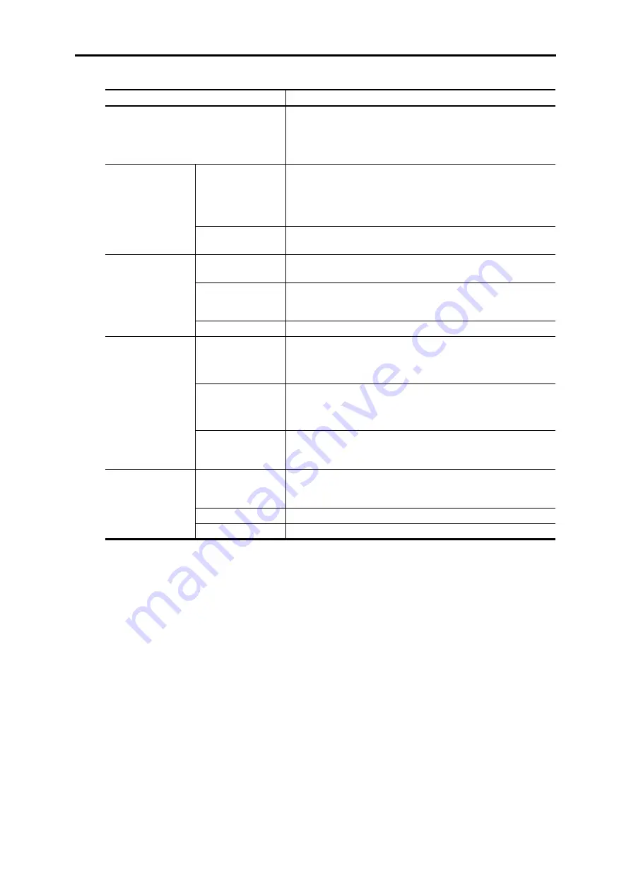
Table 6.8.2 Software Specifications
Item Specifications
Motor drive control
For induction motor: Vector control with speed sensor
Function codes P01, A01, and A101, "Drive control selection" = "0"
For synchronous motor: Vector control with speed sensor
Function codes P01, A01, and A101, "Drive control selection" = "3"
Speed control range
1:1500 (minimum speed: Base speed, 1 to 1500 r/min when converted with
4P)
1:6 (Constant torque area: constant output area, with induction motor)
May not be achieved in a synchronous motor due to electric characteristics of
the motor.
Speed control
Speed control accuracy
Analog setting: ±0.1% of maximum speed
Digital setting: ±0.005% of maximum speed
Position response
10 Hz
Response is adjusted with APR gain and ASR gain.
Position precision
Within encoder ±2 bits (At the time of steady state/ transition, F/F gain =
setting of 1.0)
With F/F gain
≠
1.0, steady state/transition deviation occurs.
Position control
(pulse train synchronous
operation)
(available soon)
Lock precision
Within encoder ± 2 bits, 150% is allowed for resistance torque.
With the motor
integrated/
directly connected
Specify function codes P01, A01, and A101 with "Drive control selection" =
"0 (induction motor)" or "3 (synchronous motor)" are set. When the SPGT
option is mounted, SPGT pulse train fed back is automatically selected to
disable the integrated PG input PA/PB terminal.
For machine axis pulse
feedback
(available in the near
future)
The machine axis position can be controlled with signals from serial PG
mounted in the machine axis.
The motor requires an independent PG to detect motor speed/position.
Serial encoder interface
function
Serial PG dedicated
alarm
Mounting this option adds the following protection functions to the standard
functions in connection with the interface with PG.
Encoder error (
et1
), encoder communication error (
ec
)
Control
Synchronous operation system
*The straight line position control system should be constructed on the
UPAC or SX (PLC) side.
Monitor
1-rotation data (17 bits), multi-rotation data (16 bits)
Position control
dedicated function
(available soon)
I/O terminal function
X function selection/Y function selection
Содержание FRENIC-VG Series
Страница 1: ...For the STACK type User s Manual User s Manual Option Edition 24A7 E 0045 3 ...
Страница 2: ......
Страница 3: ...High Performance Vector Control Inverter User s Manual Option Edition ...
Страница 155: ...6 5 SX Bus Interface Card 6 79 Chap 6 CONTROL OPTIONS Figure 6 5 5 ...
Страница 156: ...6 80 Basic Connection Diagram Figure 6 5 6 ...
Страница 203: ...6 6 High Speed Serial Communication Capable Terminal Block 6 127 Chap 6 CONTROL OPTIONS Figure 6 6 3 ...
Страница 234: ...6 158 6 7 3 External dimension drawing 17 Unit mm Figure 6 7 5 Option PCB Outline Drawing Tightening torque 0 4 N m ...
Страница 344: ......
Страница 346: ...For the STACK type User s Manual User s Manual Option Edition 24A7 E 0045 3 ...


